B-SERIES INSTALLATION, OPERATION AND SERVICE MANUAL
132 of 147
Table 27: Control Panel
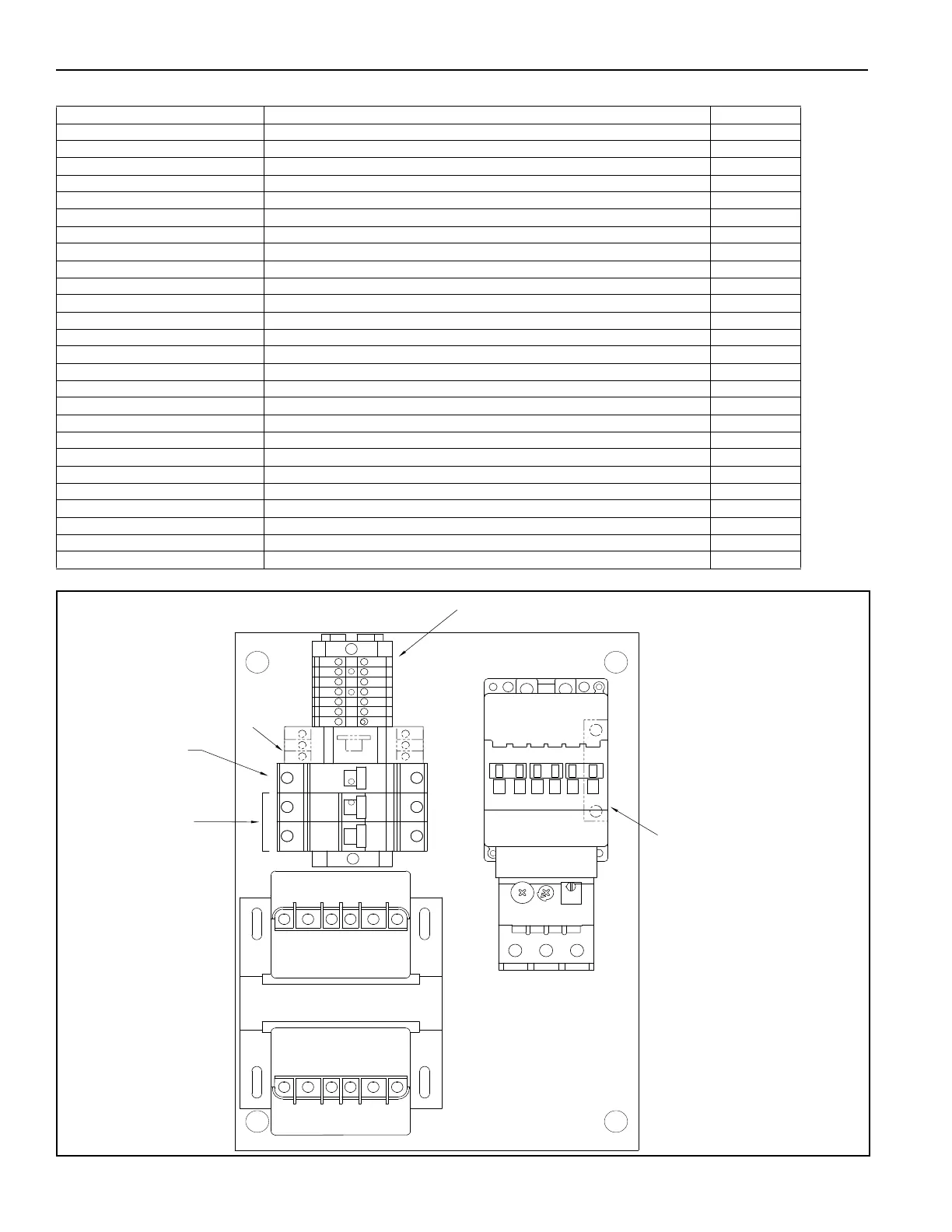
FIGURE 86: Power Panel Layout
Description Models Part Number
Pressure Switch Low Airflow All Models 90439802
Pressure Switch High Airflow All Models 90439814
Maxitrol 1014U (Temp Control Amp) Units with Basic and SDC Remotes 07332
Maxitrol 1044 (Temp Control Amp) Units with DTC Remotes 07336
Mixing Tube All Models (See Page 134, Figure 87) 07380
Discharge Air Sensor 1014 Units with Basic and SDC Remotes (not shown) (See Page 134, Figure 87) 07350
Discharge Air Sensor 1044 Units with DTC Remotes (not shown) (See Page 134, Figure 87)07410
24 V Transformer 40 VA All Models 90407100
Ignition Transformer All Models 90407219
Belimo LF120-S US 2005 and 2030 07097
Belimo NF120-S US 2010 and 2030 07095
Actuator 90 in. Lb Floating 2020 and 2030 90667110
Actuator 90 in. Lb 4-20mA 2020 and 2030 90667120
Actuator 90 in. Lb 24V 2020 and 2030 90667130
Ignition Control Module 2005 07630
Ignition Control Module RM7890 2010 and 2010B (remove jumper - See Page 112, Section 18.3.1) 07122
Ignition Control Module RM7897 2020 and 2030 (remove jumper - See Page 112, Section 18.3.1) 07130
Flame Amplifier R7849A 2010 and 2030 07123
Flame Rod 2005 07590
UV Scanner 2010 and 2030 07060
Purge Timer 7 seconds 2020 and 2030 07133
High Temperature Limit Switch All Models 07063
Igniter All Models 07640
Relay 15Amp All Models 07100
Relay 8Amp All Models 90447110
Relay Socket All Models
90447200
AUXILIARY
CONTACT
CONTACTOR
OVERLOAD
ELECTRICAL
TERMINALS
CONTROL
TRANSFORMER
TIMER
BRANCH
CIRCUIT
BREAKER
CONTROL
CIRCUIT
BREAKER