B-SERIES INSTALLATION, OPERATION AND SERVICE MANUAL
112 of 147
Table 18: Factory Preset Schedule on TH8110 Thermostat
18.2.4 BMS-Ready Control Option
The BMS-ready option provides inputs to receive
control signals from a customer determined control
system. Each BMS input is capable of receiving a
4-20mA or 0 - 10VDC from the control system. On all
air handlers, the burner modulation will be controlled
by the control system. For AM/VAV style air handlers,
the control system can also control the modulating
damper.
On DDC/BMS-ready systems, no temperature control
amplifier is installed. Discharge temperature
monitoring and modulation valve adjustment are
completed by the customer supplied control system.
For optimum efficiency, Rapid Engineering LLC
suggests to limit the discharge temperature to 160 °F.
18.3 Basic Air Handler Sequence of Operation
While the control transformer is energized, the
secondary side supplies 115 VAC to the control
circuit. When the fan switch is in the "on" position, the
M1 motor starter is energized and starts the blower
motor. The M1 motor starter auxiliary contact
supplies voltage to the burner switch and "Fan On"
light. When the burner switch is in the "on"/"winter"
position, po
wer is supplied to the flame control
module and the burner control circuit. The burner
control circuit includes the high temperature limit
switch and the low and high airflow pressure
switches. Once the burner control circuit is satisfied,
then the flame control module will execute the burner
ignition sequence. Once the pilot flame is ignited and
sensed by the UV scanner, the flame control module
will open the safety shutoff valve to ignite the main
flame. When the safety shutoff is opened, 115 VAC is
applied to the "Burner On" light and T3 transformer,
the secondary side supplies 24 VAC to the
temperature control amplifier. The temperature
control amplifier controls the modulating valve based
on the discharge temperature monitor (and also the
room temperature monitor, in the case of a DTC
remote panel).
18.3.1 Flame Control
The flame control is a safety device and not
servicable. See Page 113, Figure 73 through Page
115 , Fig u re 7 5 for detailed seq
uence of operation.
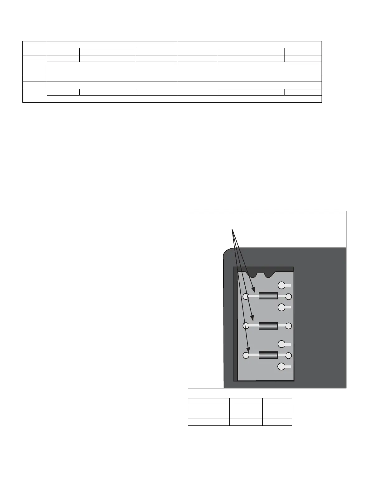
The RM 7890 and RM 7897 must be configured prior
to replacement. This is done by removing certain
configuration jumpers on the upper left corner of the
flame control, located behind the blue cover. See
Page 112, Figure 72 and Page 112, Table 19.
FIGURE 72: Honeywell Safeguard Jumpers
Table 19: Site-Configuration Jumper Options
Monday - Friday Saturday - Sunday
Time Temperature Fan Setting Time Temperature Fan Setting
Wake
6:00 AM 68° F Fan On 6:00 AM 62° F Fan Auto
The air handler will run continuously.
Temperature controlled by Maxitrol stat.
The air handler will run when the thermostat calls for heat.
Leave Unused Unused
Return Unused Unused
Sleep
5:00 PM 62° F Fan Auto 5:00 PM 62° F Fan Auto
The air handler will run when the thermostat calls for heat. The air handler will run when the thermostat calls for heat.
Jumper Number 7890 7897
JR1 Intact Intact
JR2 RemoveRemove
JR3 Intact Intact
JR1
JR2
JR3
Selectable Configuration Jumpers