SECTION 16: GAS PIPING
77 of 147
16.4 Gas Piping
The gas manifold extends through the side of the
control cabinet for models 2005 - 2030. The factory
piping terminates with a female pipe connection in
the manual gas valve. The manual main gas shutoff
valve is shipped loose for field installation. A union
must also be installed (supplied by others) between
the supplied manual gas valve main and the first tee
pipe. Be sure that the fuel supply pipe connected at
this point is large enough to ensure the proper gas
flow and line pressure at the inlet of the air handler.
The piping must comply with:
United States: Refer to NFPA 54/ANSI Z223.1 - latest
revision, National Fuel Gas Code.
Canada: Refer to CSA B149.1 - latest revision,
Natural Gas and Propane Installation Code.
Gas supply piping must conform to best building
practices and local codes. During installation of the
gas piping, be sure that no piping restricts
accessibility to the air handler or its removable
access doors.
Lockable manual shut-off val
ve must be added by the
installer in compliance with Occupational Safety and
Health Administration (OSHA) regulations.
16.5 Pressure Test Ports
There are 1/8" (3.2 mm) and 1/4" (6.4 mm) pressure
test ports located on the manifold. The test ports are
available to measure the manifold inlet gas pressure
and the burner gas pressure during burner setup.
16.5.1 Manifold Inlet Gas Pressure
The pressure port for measuring manifold inlet
pressure is located on the inlet side of the first safety
shutoff valve. Refer to the unit rating plate for the
acceptable inlet gas pressure.
16.5.2 Burner Gas Pressure
A pressure tap is used to measure negative airflow at
the burner and to set high fire gas pressure. On air
handlers equipped with a M611 modulating valve
(Model 2005), the pressure tap is located on a tee
between the M611 valve and the burner. See Page
77, Figure 36 and Page 123, Figure 81. On air
handlers equipped with the MR212 modulating valve
(Models 2010 - 2030), the pressure tap could be
located on the downstream side of the MR212 valve,
on a T-fitting coming off the outlet pressure tap on the
MR212 valve or between the MR212 valve and the
burner. See Page 77, Figure 37 and Page 122,
Figure 79.
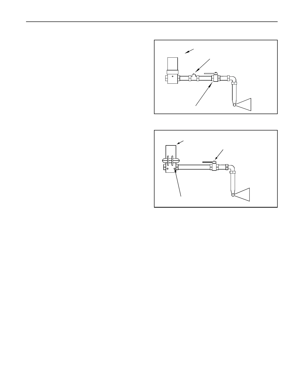
FIGURE 36: Plug Tapping (2005)
FIGURE 37: Plug Tapping (2010 - 2030)
16.6 Line Pressure Test - Leak Testing
The air handler and its individual shut-off valve must
be disconnected from the gas supply piping systems
during any pressure testing of that system at test
pressures in excess of 14 in wc (34.9 mbar). The air
handler must be isolated from the gas supply piping
system by closing its individual manual gas valv
e that
is located immediately upstream of the safety shut-off
gas valve.
Burner
Modulating Valve
Manual Gas Valve (Burner)
Plugged Taping
To Measure Burner Pressure
Burner
Modulating Valve
Manual Gas Valve (Burner)
Plugged Taping