B-SERIES INSTALLATION, OPERATION AND SERVICE MANUAL
106 of 147
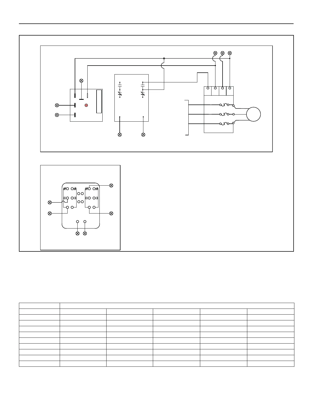
FIGURE 68: P7 30HP or More with Photohelic
17.10 Disconnect Fuse Sizing
The fuse classification must be determined by the service disconnect rating plate and all applicable codes.
Fuse sizing is determined by the motor size, control current and supply voltage. Fuses that are being
replaced must be replaced with the same type, size and class of fuse that was supplied with the air handler.
For additional information or to confirm original fuse specifications, consult the factory.
Table 16: Minimum and Maximum Fuse Size by Motor Size and Supply Voltage
Electrical Characteristics
Motor Size HP(kW) 208/3/60 230/3/60 460/3/60 575/3/60 230/1/60
2(1.5) 7.3-10.2 6.9-9.6 3.4-4.8 2.6-3.6 13.3-18.6
3(2.2) 10.1-14.2 9.3-13.0 4.6-6.5 3.7-5.2 17.3-24.2
5(3.7) 15.4-21.6 15.1-21.1 7.5-10.6 6.1-8.5 24.3-34.0
7.5(5.6) 23.1-32.4 21.3-29.8 10.6-14.9 8.3-11.6 32.3-45.2
10(7.5) 30.4-42.6 28.1-39.3 14.0-19.7 10.6-14.8 40.3-56.4
15(11.2) 42.4-59.4 39.3-55.0 19.6-27.5 16.8-23.5 -
20(14.9) 51.4-72.0 49.3-69.0 24.6-34.5 19.8-27.7 -
25(18.6) 66.4-93.0 61.3-85.8 30.6-42.9 24.5-34.3 -
30(22.4) 78.4-109.8 73.3-102.6 36.6-51.3 29.6-41.4 -
2
RELAY
R1
MOTOR
OL
VFD
EXHAUST
MOTOR(S)
T1
T2
T3
S1
S5
SN
L1
L2
L3
S3
OL
OL
TO CUSTOMER
SUPPLIED
DISCONNECT
AND FUSING
3C
50
52
51
50
(L1)
(L2)
HIGH
(ACCEL)
PHOTOHELIC
LOW
(DECEL)
52
53
3C
2
54
50
53
LOCATED ON VFD PANEL INSIDE CONTROL ENCLOSURE
PHOTOHELIC LOCATED INSIDE SEPARATE REMOTE ENCLOSURE
PRESET AT 0.1"(LOW) AND 0.3"(HIGH)
CONTROLS BOOTH PRESSURE
52
50
2
50
52
3C
54
INCREASE
OVERRIDE
TIMER
TD7
SET TO 60 SEC