SECTION 19: START-UP PROCEDURES
119 of 147
adjustment.
Table 21: Motor Sheave Drive Torque
Specifications
Table 22: Motor and Blower Bushing Torq ue
Specifications
19.4.2 Burner Pressure
1. A pressure tap is used to measure differential
at the burner and to set high fire gas pressure.
On air handlers equipped with a M611 modu-
lating valve (Model 2005), the pressure tap is
located on a tee between the M611 valve and
the burner. See Page 77, Figure 36 and Page
123, Figure 81. On air handlers equipped with
the MR212 modulating valve (Models 2010 -
2030), the pressure tap could be located on the
downstream side of the MR212 valve, on a T-
fitting coming off the outlet pressure tap on the
MR212 valve or between the MR212 valve and
the burner. See Page 77, Figure 37
and Page
122, Figure 79.
2. Measure the burner pressure with the inlet
manual gas valve off.
- Open the manual shut off located between
the modulating valve and the burner.
- Turn the blower on and record the negative
pressure on a u-tube manometer or gas
pressure gauge. This reading is used for high
fire burner pressure adjustment.
3. After taking the burner pressure reading, tem-
porarily leave the manometer attached to the
1/8" tap. It will be used later to check high fire
gas pressure.
19.5 Gas Piping and Initial Pressure Settings
1. Perform a pressure test on all gas supply lines
to the air handler per applicable codes.
Make sure to isolate all gas controls before
pressure testing the system.
2. Verify supply pressu
re does not exceed maxi-
mum rated gas pressure as stated on the rating
plate.
3. Set the supply gas pressure at the step down
regulator (normally outside of the enclosure if
one is installed) according to the nameplate
rating inlet gas pressure specifications.
4. Only after performing steps 1-3 (above), verify
pilot pressure.
•Place a u-tube manometer or gas pressure
gau ge on the tee at the downstream side of
the pilot pressure regulator.
• Open the main gas valve and close the gas
valve downstream of the MR valve.
•Set the burner switch to "on" and adjust the
pilot pressure regulator to 1.0 in wc for
natural gas or 0.5 in wc for LPG.
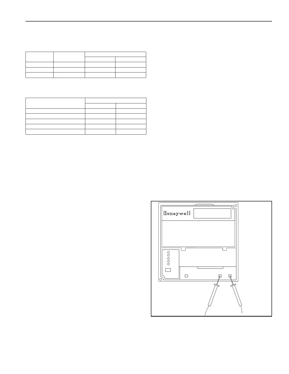
• Verify that the burner flame control has a
flame signal of 5.0 VDC / 2010 - 2030.
See
Page 119, Figure 78
.
FIGURE 78: Honeywell Flame Module
Setscrew Size Allen Wrench
Torque Settings
in
•Lbs ft•Lbs
1/4" 1/8" 87 7.3
5/16" 5/32" 120 10.0
3/8" 3/16" 290 24.2
Bolt Size (on Bushing)
Torque Settings
in
•Lbs ft•Lbs
#10 60 5
1/4" 108 9
5/16" 192 16
3/8" 360 30
1/2" 720 60
BURNER CONTROL
BURNER FLAME CONTROL
FLAME AMPLIFIER
+
-
- Negative + Positive
5.0 VDC