Flathead
Screws
Screw
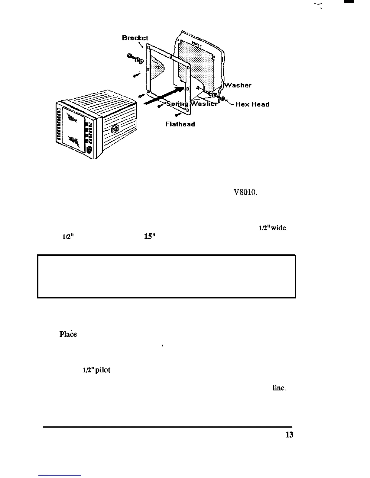
232.1 Console Mounting Instructions
The procedure below can be used to console mount the
V8010.
Refer to
the console mounting figure above to see how the various hardware items
are arranged during assembly.
1. Select the location for the unit. A clear, flat area of at least 11
Wwide
by 9
lL2”
high having at least
15”
of clearance depth behind the panel is
required.
CAUTION
Make sure there are no hidden electrical wires or other items behind the
desired location before proceeding. Check that free access for mounting
and cabling is available.
2. Unpack the console mounting kit and confirm that all hardware is
present.
3.
Pla6e
the trim ring over the desired location on the panel. Using the
inside of the trim ring as guide
,
trace the perimeter for the cutout.
Remove the trim ring.
4. Drill a 1E’pilot hole in each opposing corners of the cut-out area.
5. Using an appropriate saw, cut along the outside edge of the cut-out
line.
INSTALLATION
l3
 Loading...