The Sensor
DA
T
A
INPUT wire (pin 5)
should also be connected to the GPS
connector so that the echo sounder can provide initializing data input to the
GPS sensor unit.
2.4.4
Sea%lk
Interface
Sea’ltilk
is a system of data interchange between
Autohelm
Instruments
and Autopilots and other Sealhlk compatible units. The system is linked
serially by a single cable containing three wires. The wires used are 1) 12
VDC supply, 2) a bi-directional data line, and 3) ground.
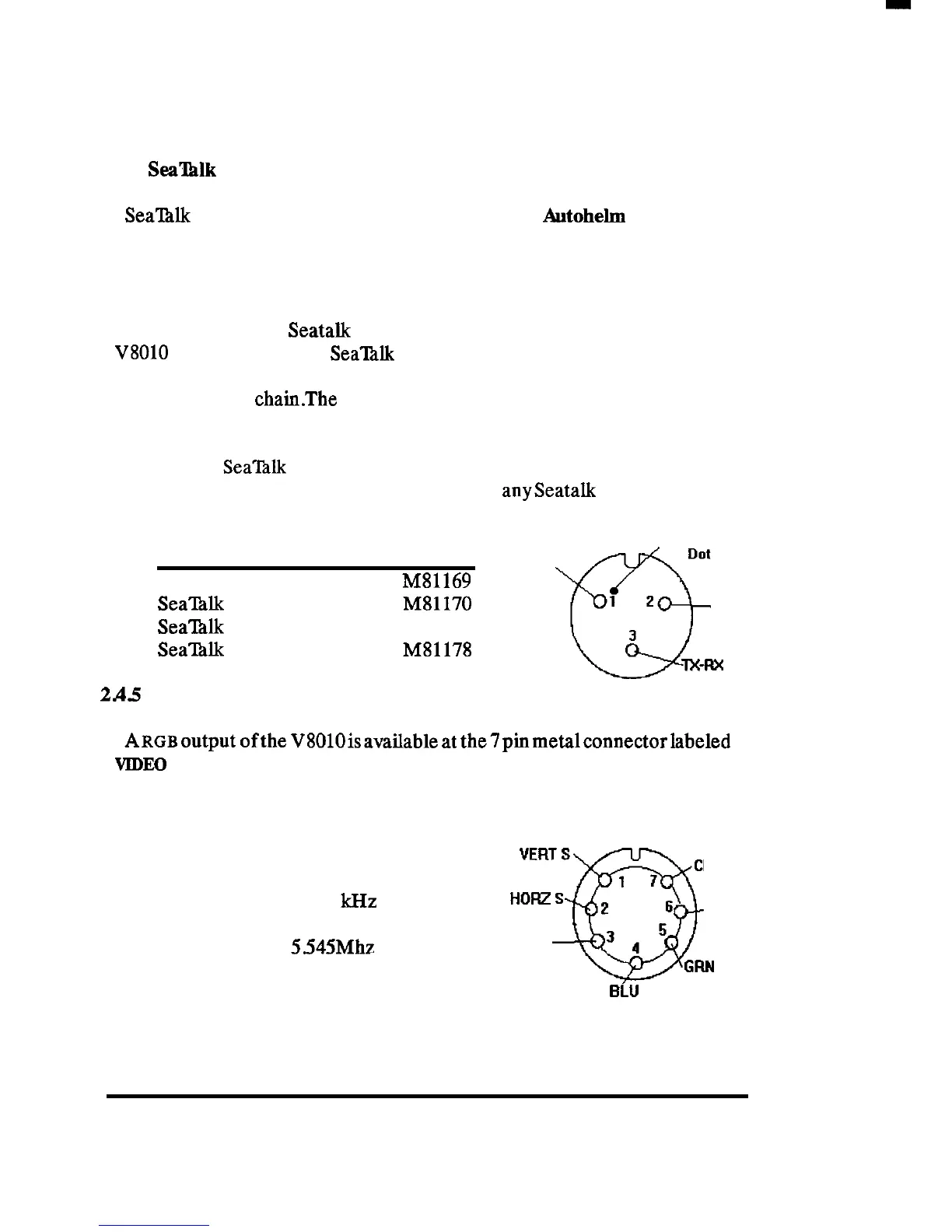
When the optional
Seatalk
Interface Kit (M78860) is installed, and the
V8010
is connected to the
SeaTalk
bus via the 3 pm micro connector on the
unit rear panel, the echo sounder will interface directly to the free end of
the Sealhlk data
chainThe
connections for the 3 pm connector are shown
in the diagram.
Convenient
Sea’l%lk
cable assemblies are available at various lengths from
Raytheon/ Autohehn dealers to help complete
anyseatalk
interconnection
requirements as follows:
Locating
ITEM
LENGTH P/N
Dot
Sealhlk Cable
3 Foot
vcc
MS1169
SeaINk Cable
10 Foot M81170
1 2
Gnd
Sea’lhlk
Cable
30 Foot
M81171
Q
3
Seal?&
Y Cable 1 Foot
M81178
TX-R%
Data
2A5
Video Output
[Solder Side]
View from solder side
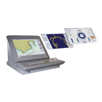
A~~~output
ofthe
V8010isavailableat
the7pinmetalconnectorlabeled
VIDEO
OUT on the unit’s rear panel. This output can be used to operate a
separate remote RGB color display.
The picture will be portrait oriented on the
VIDEO OUTPUT
remote display.
VERT
S
CLOCK
1 7
Horizontal Sync = 15.75 kHz
HORZS
2
6
RED
Vertical Sync
= 60Hz
Dot Clock
=
5.545Mhz
GND
0
32
GFIN
BLU
View from solder side
INSTALLATION 19