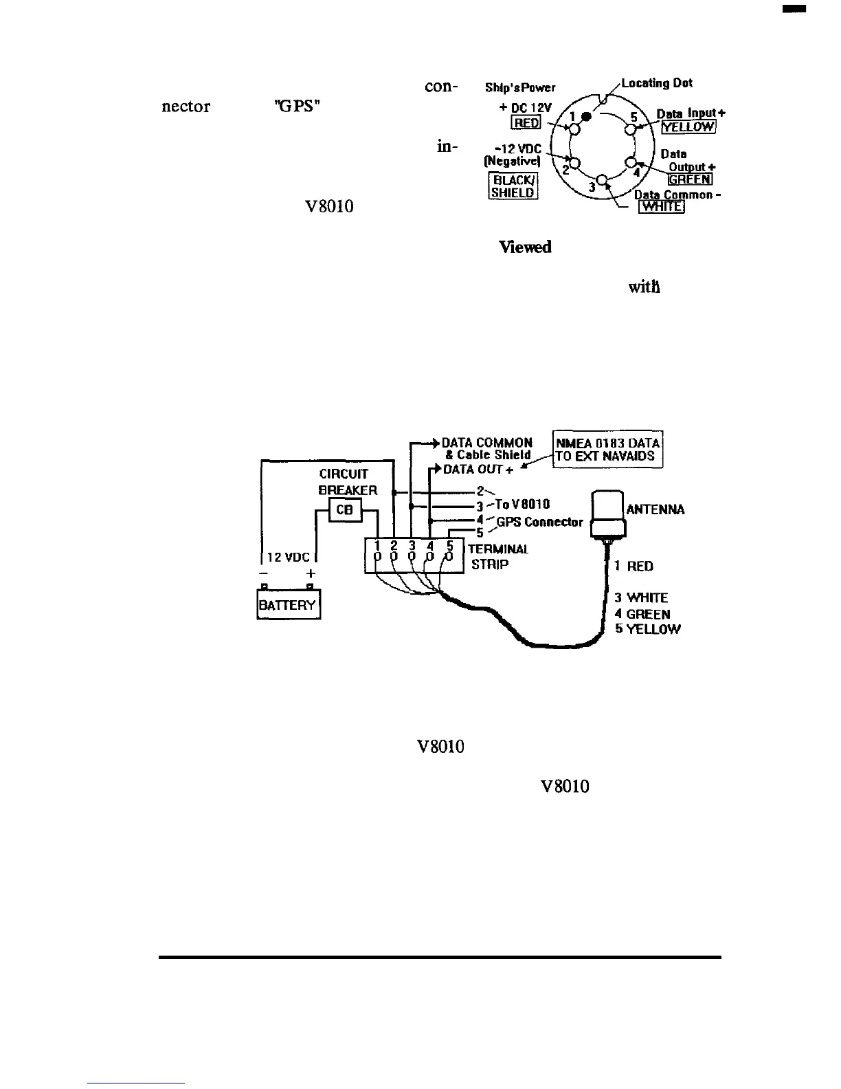
In a typical installation the 5 pm an-
tenna connector is plugged into the
con-
nectar labeled
‘FPS”
on the rear of the
cabinet. Other external navigation
equipment requiring GPS position
in-
puts normally can obtain the required
NMEA 0183 data via the Data Output
connection of the
V8010
via the 6 pm
Data cable.
Viewed
from solder side
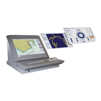
However, there may be an occasion
where it is desirable to operate the GPS sensor unit directly
with
other
navigation equipment capable of accepting GPS input data. In this case,
the GPS sensor cable could be terminated at a terminal strip outside of the
video sounder and cabled according to the configuration shown in the
drawing below. The GPS sensor provides GLL, VTG, RMC, and GGA
NMEA 0183 sentences in it’s output.
2
BLACK/SHIELD
In this installation the ship’s DC power is applied directly to the GPS
sensor through a circuit breaker and/or distribution switch.
This permits
the
sensor to be used even though the
V8010
is turned OFF.
The Sensor DATA OUTPUT is provided both to the
V8010
GPS connector
input and in parallel to the external navigation equipment. Please note that
the GPS sensor output is only guaranteed to drive 2 (two) devices directly.
Verify also that the data lines are not grounded at any of the external
equipment.
INSTALLATION 18