To
reduce drag, best results are obtained with sharp vertical leading edge
fairings because their wedge shape helps to divert aerated water off to the
sides of the transducer and not over the acoustic window.
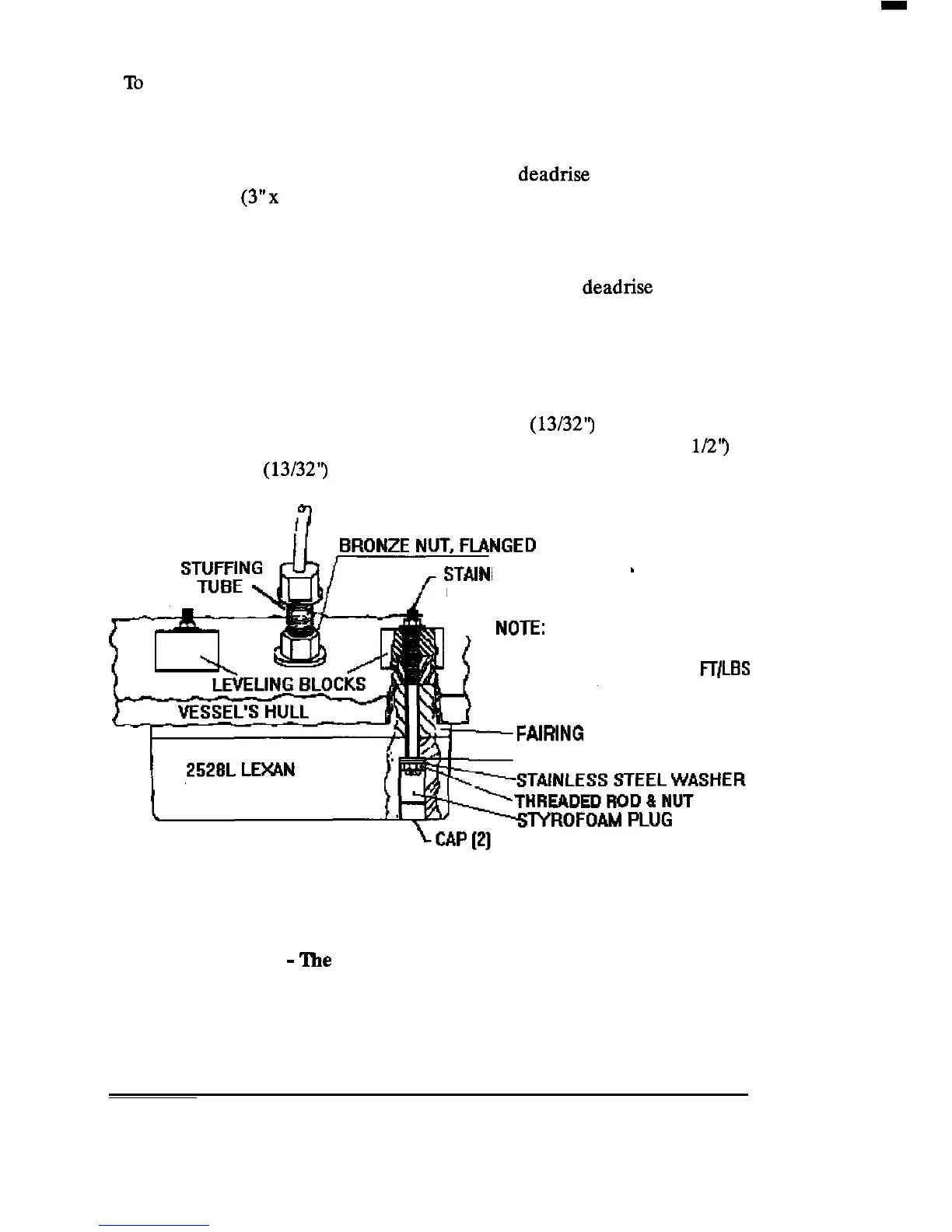
After the fairing block has been shaped to the
deadrise
of the hull, a 77
mm x 150 mm
(3”~
6’3 hole should be cut through the center of the fairing
block to allow for cable routing and service loop, and to make room for the
stuffing tube that leads the cable into the hull.
Backing blocks should be fabricated using the interior deadrise angle on
bottom of block and a level surface on the top of the block for mounting
hardware for each of the two rods that hold the transducer in place. Boat
yards are generally equipped to fabricate fairing and backing blocks.
Place the transducer over the fairing block and mark the two transducer
mounting hold locations. Drill the two 10 mm
(13/32”)
diameter holes
through the fairing block. Counterbore these holes to 39 mm (1
112”)
diameter, 10 mm
(13/32”)
deep, from the transducer side.
LESS STEEL ROD
NUT, AND WASHERS
BOLTS SHOULD BE TORQUED
TO NOT MORE THAN
10
Ff/LBS
FAMNG
BLOCK
RUBBER WASHER
TRANSDUCER
TYPICAL LEXAN TRANSDUCER
INSTALLATION
2533 Preparation 3
-
The
Location.
(For Fiberglass or Wood Hull Installation)
(Safety Goggles and Dust Mask should be worn when drilling)
INSTALLATION 25