RL78/F13, F14 CHAPTER 6 TIMER ARRAY UNIT
R01UH0368EJ0210 Rev.2.10 434
Dec 10, 2015
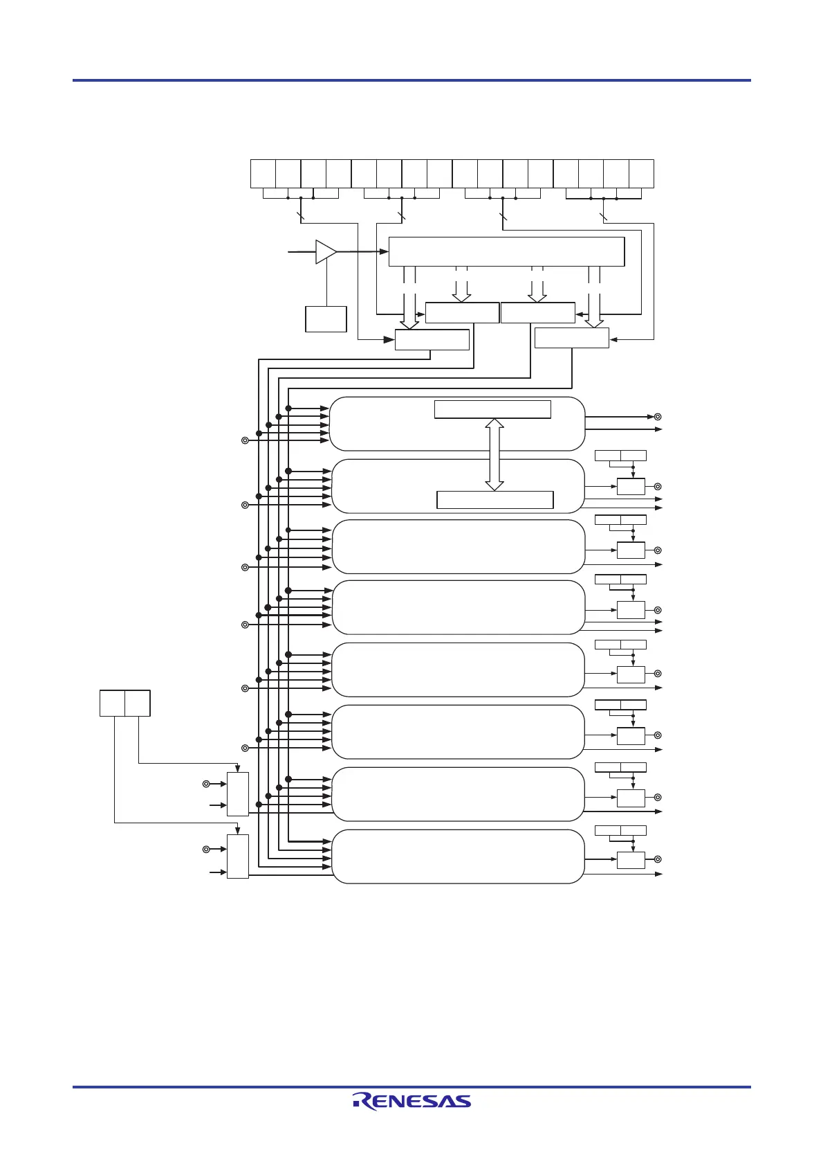
Figure 6-3. Entire Configuration of Timer Array Unit 1 (Example: Group E)
4
4
44
fCLK
TAU1EN
PRS133 PRS132 PRS131 PRS130 PRS123 PRS122 PRS121 PRS120 PRS113 PRS112 PRS111 PRS110 PRS103 PRS102 PRS101 PRS100
f
CLK
/2
0
- f
CLK
/2
15
f
CLK
/2
0
- f
CLK
/2
15
f
CLK
/2
0
- f
CLK
/2
15
f
CLK
/2
0
- f
CLK
/2
15
CK13 CK12 CK11 CK10
TI10
TI11
TI12
TI13
TI14
TI15
TI16
RTC1HZ
TI17
RTC1HZ
TIS22TIS23
TO10
INTTM10
INTTM1
1
INTTM12
INTTM1
1H
INTTM13
INTTM14
INTTM15
INTTM16
INTTM17
INTTM13H
TO11
TO12
TO13
TO14
TO15
TO
16
TO
17
TO171 TO170
TO161 TO160
TO151 TO150
TO141 TO140
TO131 TO130
TO121 TO120
TO111 TO110
PWM output delay control register 2
(PWMDLY2)
PWM output delay control register 2
(PWMDLY2)
PWM output delay control register 2
(PWMDLY2)
PWM output delay control register 2
(PWMDLY2)
PWM output delay control register 2
(PWMDLY2)
PWM output delay control register 2
(PWMDLY2)
PWM output delay control register 2
(PWMDLY2)
Timer input select register 2 (TIS2)
Selector Selector
Timer clock select register 1 (TPS1)
Peripheral enable
register 0 (PER0)
Prescaler
Selector Selector
Selector
Selector
Slave/master controller
Slave/master controller
Channel 0
Channel 1
Channel 2
Channel 3
Channel 4
Channel 5
Channel 6
Channel 7
Delay
controller
Delay
controller
Delay
controller
Delay
controller
Delay
controller
Delay
controller
Delay
controller
 Loading...


