RL78/F13, F14 CHAPTER 6 TIMER ARRAY UNIT
R01UH0368EJ0210 Rev.2.10 446
Dec 10, 2015
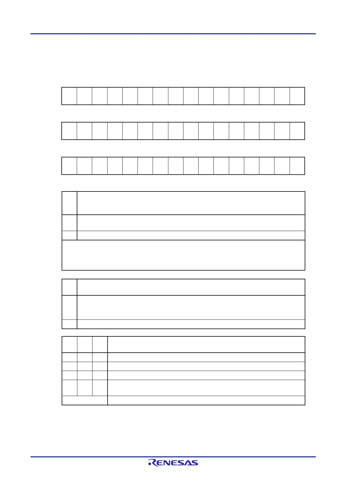
Figure 6-13. Format of Timer Mode Register mn (TMRmn) (2/4)
Address: F0190H, F0191H (TMR00) to F019EH, F019FH (TMR07), After reset: 0000H R/W
F01D0H, F01D1H (TMR10) to F01DEH, F01DFH (TMR17)
Symbol 15 14 13 12 11 10 9 8 7 6 5 4 3 2 1 0
TMRmn
(n = 2, 4, 6)
CKS
mn1
CKS
mn0
0
CCS
mn
MAST
ERmn
STS
mn2
STS
mn1
STS
mn0
CIS
mn1
CIS
mn0
0 0
MD
mn3
MD
mn2
MD
mn1
MD
mn0
Symbol 15 14 13 12 11 10 9 8 7 6 5 4 3 2 1 0
TMRmn
(n = 1, 3)
CKS
mn1
CKS
mn0
0
CCS
mn
SPLIT
mn
STS
mn2
STS
mn1
STS
mn0
CIS
mn1
CIS
mn0
0 0
MD
mn3
MD
mn2
MD
mn1
MD
mn0
Symbol 15 14 13 12 11 10 9 8 7 6 5 4 3 2 1 0
TMRmn
(n = 0, 5, 7)
CKS
mn1
CKS
mn0
0
CCS
mn
0
Note
STS
mn2
STS
mn1
STS
mn0
CIS
mn1
CIS
mn0
0 0
MD
mn3
MD
mn2
MD
mn1
MD
mn0
(Bit 11 of TMRmn (n = 2, 4, 6))
MAS
TER
mn
Selection between using channel n independently or
simultaneously with another channel(as a slave or master)
0
Operates in independent channel operation function or as slave channel in simultaneous channel operation
function.
1 Operates as master channel in simultaneous channel operation function.
Only channels 2, 4, and 6 can be set as a master channel (MASTERmn = 1).
Channels 0, 5, and 7 are fixed to 0 (channel 0 always operates as master regardless of the bit setting, because it is
the highest channel).
Clear the MASTERmn bit to 0 for a channel that is used with the independent channel operation function.
(Bit 11 of TMRmn (n = 1, 3))
SPLI
Tmn
Selection of 8 or 16-bit timer operation for channels 1 and 3
0 Operates as 16-bit timer.
(Operates in independent channel operation function or as slave channel in simultaneous channel operation
function.)
1 Operates as 8-bit timer.
STS
mn2
STS
mn1
STS
mn0
Setting of start trigger or capture trigger of channel n
0 0 0 Only software trigger start is valid (other trigger sources are unselected).
0 0 1 Valid edge of the TImn pin input is used as both the start trigger and capture trigger.
0 1 0 Both the edges of the TImn pin input are used as a start trigger and a capture trigger.
1 0 0
Interrupt signal of the master channel is used (when the channel is used as a slave channel
with the simultaneous channel operation function).
Other than above Setting prohibited
Note Bit 11 is a read-only bit and fixed to 0. Writing to this bit is ignored. In addition, channel 0 operates as master.
Remarks 1. m: Unit number (m = 0, 1), n: Channel number (n = 0 to 7)
2. TMR1n is not provided in the Group A products.
TMR17 to TMR14 are not provided in the Group B, C, and D products.
 Loading...


