RL78/F13, F14 CHAPTER 6 TIMER ARRAY UNIT
R01UH0368EJ0210 Rev.2.10 482
Dec 10, 2015
(2) Default level of TOmn pin and output level after timer operation start
The change in the output level of the TOmn pin when timer output register m (TOm) is written while timer output is
disabled (TOEmn = 0), the initial level is changed, and then timer output is enabled (TOEmn = 1) before port output
is enabled, is shown below.
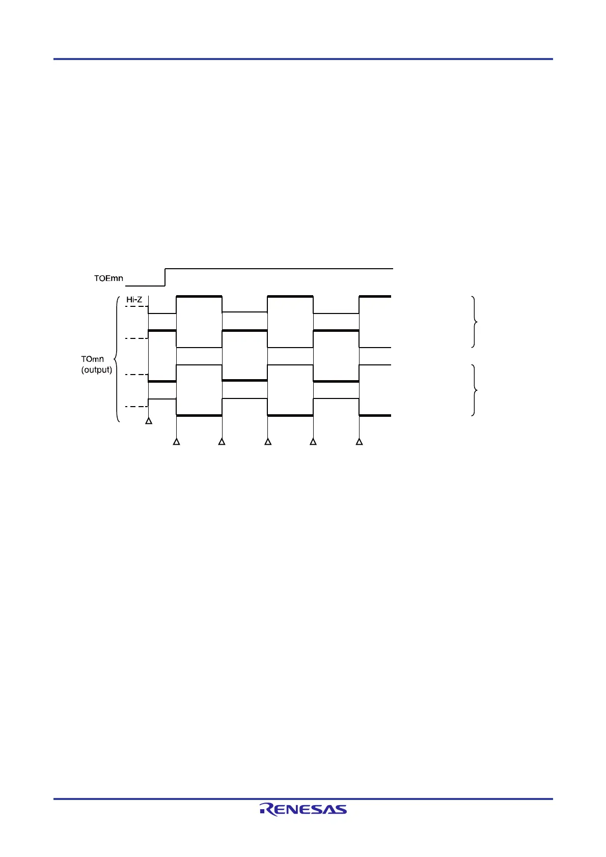
(a) When operation starts with master channel output mode (TOMmn = 0) setting
The setting of timer output level register m (TOLm) is invalid when master channel output mode (TOMmn = 0).
When the timer operation starts after setting the default level, the toggle signal is generated and the output level
of the TOmn pin is reversed.
Figure 6-36. TOmn Pin Output Status at Toggle Output (TOMmn = 0)
Remarks 1. Toggle: Reverse TOmn pin output status
2. m: Unit number (m = 0, 1), n: Channel number (n = 0 to 7)
3. Unit 1 is not provided in the Group A products.
Channels 7 to 4 of unit 1 are not provided in the Group B, C, and D products.
TOmn bit = 0
(Default status : Low)
Default
status
Port output is enabled
To
le To
leTo
leTo
leTo
le
Bold : Active level
TOmn bit = 1
(Default status : High)
TOmn bit = 0
(Default status : Low)
TOmn bit = 1
(Default status : High)
TOmn bit = 0
(Active high)
TOmn bit = 1
(Active low)
 Loading...


