RL78/F13, F14 CHAPTER 6 TIMER ARRAY UNIT
R01UH0368EJ0210 Rev.2.10 483
Dec 10, 2015
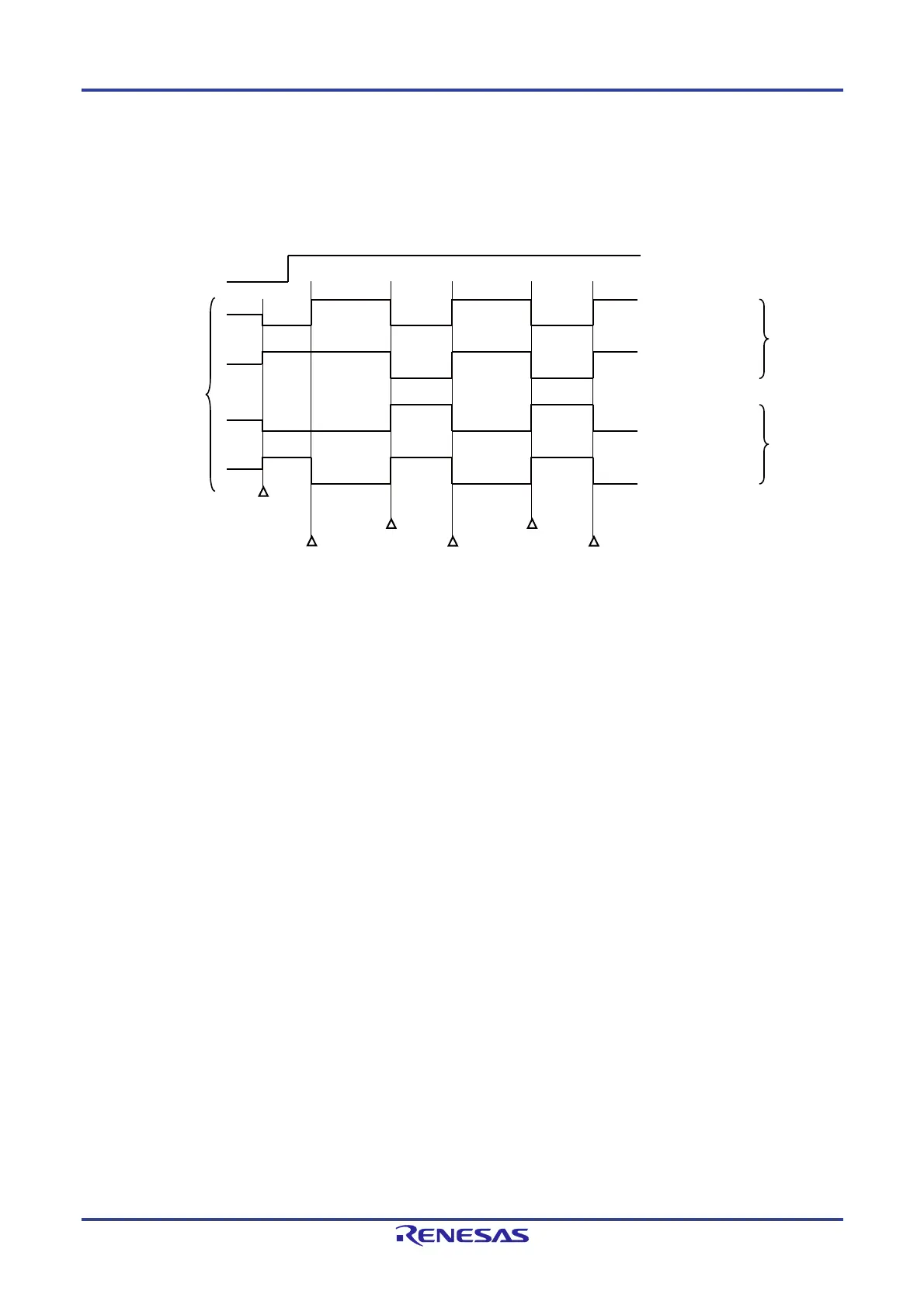
(b) When operation starts with slave channel output mode (TOMmn = 1) setting (PWM output))
When slave channel output mode (TOMmn = 1), the active level is determined by timer output level register m
(TOLm) setting.
Figure 6-37. TOmn Pin Output Status at PWM Output (TOMmn = 1)
Remarks 1. Set: The output signal of the TOmn pin changes from inactive level to active level.
Reset: The output signal of the TOmn pin changes from active level to inactive level.
2. m: Unit number (m = 0, 1), n: Channel number (n = 0 to 7)
3. Unit 1 is not provided in the Group A products.
Channels 7 to 4 of unit 1 are not provided in the Group B, C, and D products.
Hi -Z
Active
TOEmn
Default
status
Set
Reset
Set
Reset
Set
Port output is enabled
TOmn
(output)
ActiveActive
TOmn bit = 0
(Default status : Low)
TOmn bit = 1
(Default status : High)
TOmn bit = 0
(Default status : Low)
TOmn bit = 1
(Default status : High)
TOLmn bit = 0
(Active high)
TOLmn bit = 1
(Active low)
 Loading...


