RL78/F13, F14 CHAPTER 8 TIMER RD
R01UH0368EJ0210 Rev.2.10 619
Dec 10, 2015
(3) Synchronous Operation
The TRD1 register is synchronized with the TRD0 register
Synchronous preset
When the TRDSYNC bit in the TRDMR register is set to 1 (synchronous operation), the data is written to both the
TRD0 and TRD1 registers after writing to the TRDi register.
Synchronous clear
When the TRDSYNC bit is 1 and bits CCLR2 to CCLR0 in the TRDCR0 register are 011B (synchronous clear), the
TRD0 register is set to 0000H at the same time as the TRD1 register is set to 0000H.
Also, when the TRDSYNC bit is 1 and bits CCLR2 to CCLR0 are 011B (synchronous clear), the TRD1 register is
set to 0000H at the same time as the TRD0 register is set to 0000H.
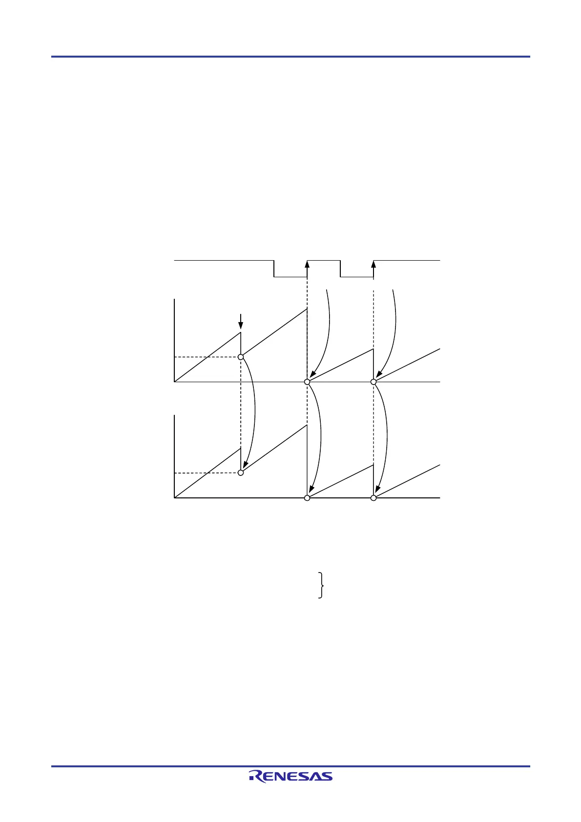
Figure 8-43. Synchronous Operation
n
n
TRDIOA0 input
Value in
TRD0 register
Value in
TRD1 register
n is set
n is set
n writing
Set to 0000H by input capture
Set to 0000H in synchronization with TRD0
The above diagram applies under the following conditions:
• The TRDSYNC bit in the TRDMR register is set to 1 (synchronous operation).
• Bits CCLR2 to CCLR0 in the TRDCR0 register are set to 001B (TRD0 is set to 0000H by input capture).
Bits CCLR2 to CCLR0 in the TRDCR1 register are set to 011B (TRD1 is set to 0000H in synchronization with TRD0).
• Bits IOA2 to IOA0 in the TRDIORA0 register are set to 100B.
• Bits CMD1 to CMD0 in the TRDFCR register are set to 00B.
The PWM 3 bit in the TRDFCR register is set to 1.
(Input capture at the rising edge of TRDIOA0 input)
 Loading...


