RL78/F13, F14 CHAPTER 21 INTERRUPT FUNCTIONS
R01UH0368EJ0210 Rev.2.10 1481
Dec 10, 2015
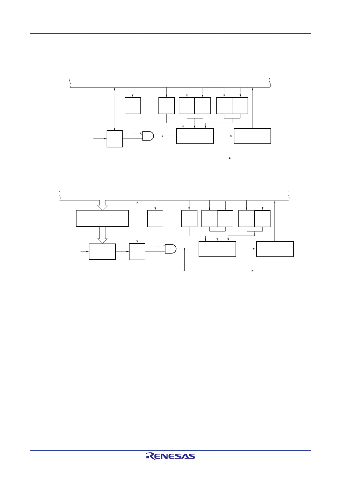
Figure 21-1. Basic Configuration of Interrupt Function (1/3)
(A) Internal maskable interrupt
(B) External maskable interrupt (INTPm)
IF: Interrupt request flag
IE: Interrupt enable flag
ISP0: In-service priority flag 0
ISP1: In-service priority flag 1
MK: Interrupt mask flag
PR0: Priority specification flag 0
PR1: Priority specification flag 1
Remark n = 0, 1
20-pin: m = 0 to 4
30-, 32-pin: m = 0 to 5
48-pin: m = 0 to 9
Note 1
64-pin: m = 0 to 12
Notes 1, 2
80-, 100-pin: m = 0 to 13
Note 2
Notes 1. Group A products: m = 0 to 7
2. Products of Groups B to D: m = 0 to 11
IF
MK IE PR1
ISP1
PR0
ISP0
Internal bus
Interrupt
request
Priority controller
Vector table
address generator
Standby release
signal
IF
MK IE PR1
ISP1
PR0
ISP0
Internal bus
External interrupt edge
enable register n
(EGPn, EGNn)
INTPm pin input
Edge
detector
Priority controller
Vector table
address generator
Standby release
signal
 Loading...


