RL78/F13, F14 CHAPTER 27 SAFETY FUNCTIONS
R01UH0368EJ0210 Rev.2.10 1593
Dec 10, 2015
(5) ECC test mode register (ECCTMDR)
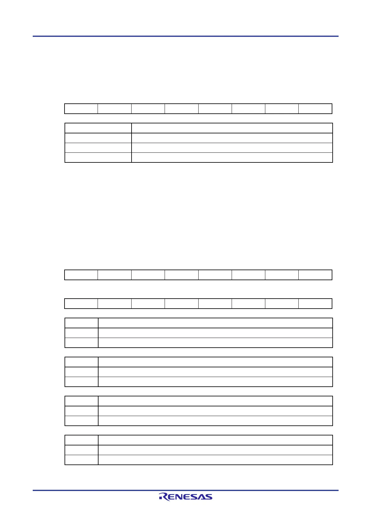
Figure 27-12. Format of ECC Test Mode Register (ECCTMDR)
Address: F0205H After reset: 00H R/W
Symbol 7 6 5 4 3 2 1 0
ECCTMDR - - - - - TMD2 TMD1 TMD0
TMD2 to TMD0 ECC test mode bits
000 Normal operating mode
001 ECC test mode
Other than above Setting prohibited
Cautions 1. Set the ECCTPR register to "07H" before accessing the ECCTMDR register.
2. Bits 3 to 7 of the ECCTMDR register are always read as 0. The write value should always be
0.
(6) Write data inversion register (ECCDWRVR)
This register is for use in confirming that the ECC is operating correctly by inverting both the parity bit of the write data
and the ECC code.
Figure 27-13. Format of Write Data Inversion Register (ECCWRDR)
Address: F0206H After reset: 0000H R/W
Symbol 15 14 13 12 11 10 9 8
ECCWRVR - - - PRTYRV ECCRV3 ECCRV2 ECCRV1 ECCRV0
Symbol 7 6 5 4 3 2 1 0
ECCWRVR DWRV7 DWRV6 DWRV5 DWRV4 DWRV3 DWRV2 DWRV1 DWRV0
PRTYRV Parity inversion bit
0 Parity bit not inverted.
1 Parity bit inverted.
ECCRV3 ECC code inversion bit 3
0 Bit 3 of ECC code not inverted.
1 Bit 3 of ECC code inverted.
ECCRV2 ECC code inversion bit 2
0 Bit 2 of ECC code not inverted.
1 Bit 2 of ECC code inverted.
ECCRV1 ECC code inversion bit 1
0 Bit 1 of ECC code not inverted.
1 Bit 1 of ECC code inverted.
 Loading...


