7. OPERATING ADDITIONAL FUNCTIONS
7-2 IMR02C15-E4
7.1 SV Selection Function (Step SV function)
The SV selection function enables control by switching to any one of the stored set values of up to
four points (SV1 to SV4). The Set value (SV) selecting can be made by digital input (DI) [optional] or
communication [optional] other than the key operation.
For SV selection by digital input (DI), refer to SV selection by digital input (DI) (P. 7-4).
For SV selection by communication, refer to Communication Instruction Manual
(IMR02C16-E).
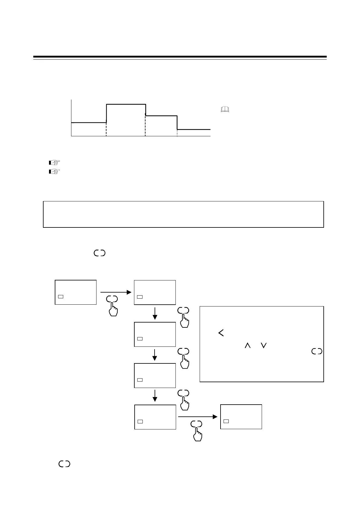
Setting procedure
Before operation, set the Set values 1 (SV1) to 4 (SV4) that are used in SV selection and choose which
SV (among SV1 and SV4) will be used to start control.
Press and hold the key for 2 seconds or more at the PV/SV monitor screen to go to the Parameter
setting mode and set the control set value in the screen of SV1 to SV4.
• Return to the PV/SV monitor
To return the PV/SV monitor, press and hold
the key for 2 seconds or more.
One of the 4 set values can be selected and used
for control. [Factory set value: 1 (SV1)]
For SV selection method, refer to SV selection
by front key operation (P. 7-3) or
SV selection by digital input (DI) (P. 7-4).
SET
SET
SV1 to SV4 setting range:
Setting limiter low to Setting limiter high
[Factory set value: 0 (0.0)]
PV/SV monitor
28$
150
SV1
SV1
0150
SV1
2 seconds or more
SV2
0000
SV1
SV4
0000
SV1
SV3
0000
SV1
Parameter setting mode
Set value 1 (SV1)
Set value 2 (SV2)
Set value 4 (SV4)
Set value 3 (SV3)
S-SV
0001
SV1
Displays the next parameter
SV selection
SET
SET
SET
SET
SET
Power ON
or RUN
Set value (SV)
SV1
SV2
SV3
SV4
Selected to
SV2
Selected to
SV3
Selected to
SV4
The application of the SV selection
function
The SV selection function can be used i
combination with the Timer function fo
ramp/soak control. For Timer function, refe
to 7.2 Timer function (P. 7-5).
The parameter for the SV selection function is not displayed in the factory default setting. Before enabling the
function, set “0: Display” in the F01 block selection (no display) (
S.F01
) parameter of Function block 01 (F01) of
Engineering mode. For the setting procedure, refer to
Hiding the parameters of the Parameter setting mode (P. 6-37).
Set value change and registration
• The blinking digit indicates which digit can be
set. The blinking digit can be moved by pressing
the key.
•
However, the changed data is not stored by the
operation of the and keys alone. In order
for the new parameter value to be stored, the
key must be pressed within 1 minute after the
new value is displayed. The new value will then
be saved and the display will move to the next
parameter.
R/S
SET

 Loading...


