8. PARAMETER DESCRIPTION
IMR02C15-E4
8-51
Function block (F) structure in the Engineering mode
Setting items are classified into groups (Function block: F) within the Engineering mode.
Function block 00 (F00)
No display screen settings (Monitor display mode, Mode switching), set lock level settings for
the Setting data lock function, and RUN/STOP switching in Engineering mode can be selected.
Function block 01 (F01) to Function block 10 (F10)
The parameter setting screen that is displayed in Parameter setting mode can be hidden.
Some setting items in Parameter setting mode are the same as the items in F01 to F10. When the
set value of one of these items is changed, the set value of the corresponding item in the other
mode also changes.
If the setting data is locked, the data cannot be changed.
Function block 21 (F21) to Function block 91 (F91)
Settings related to the specifications of this product can be selected.
Parameters from F21 to F91 are not displayed. To display these parameters, set “128” to the
Mode selection (no display) [MODE] at F00.
If the setting data is locked, the data cannot be changed.
Display or setting of parameters in F21 to F91 is not available when the setting data is
locked.
If the controller is RUN state, the data of F21 to F91 cannot be changed.
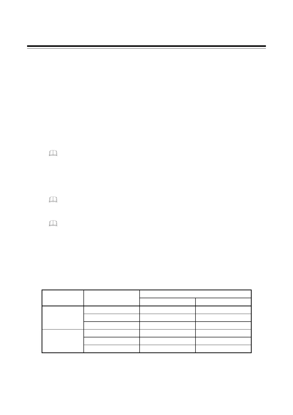
Restricting access to the Engineering mode
Access on display and setting is limited in the Engineering mode. When the setting data is locked by
the Data lock function, the data is not displayed. Refer to the table below for access restrictions in the
Engineering mode:
◎: Can be displayed and change : Can be displayed : Cannot be displayed or change
RUN/STOP
Set data unlock/
lock transfer
Engineering mode
RUN STOP (STOP lamp lights)
F00
◎ ◎
F01 to F10
◎ ◎
Unlock
F21 to F91
◎
F00
◎ ◎
F01 to F10 *
◎ ◎
Lock
(! lamp lights)
F21 to F91
* Settings can be changed within the parameters in the unlocked function blocks.
(Excluding F91)

 Loading...


