8. PARAMETER DESCRIPTION
IMR02C15-E4
8-52
8.5.2 Precaution against parameter change
If any of the following parameters are changed, the set values of relevant parameters are initialized or
automatically converted according to the new setting. It may result in malfunction or failure of the
instrument.
− Input type (InP) − Decimal point position (PGdP)
− Transmission output type (Ao) − Input scale high (PGSH)
− Event 1 type (ES1) − Input scale low (PGSL)
− Event 2 type (ES2) − Setting limiter high (SLH)
− Event 3 type (ES3) − Setting limiter low (SLL)
− Event 4 type (ES4) − Communication protocol (CMPS)
− Output limiter high (oLH) − Timer time unit (FMU)
− Output limiter low (oLL)
Before changing any parameter setting on the above list, always record all parameter
settings in SV setting mode, Parameter setting mode and Engineering mode.
And after the change, always check all parameter settings in SV setting mode,
Parameter setting mode and Engineering mode by comparing them with the record
taken before the change.
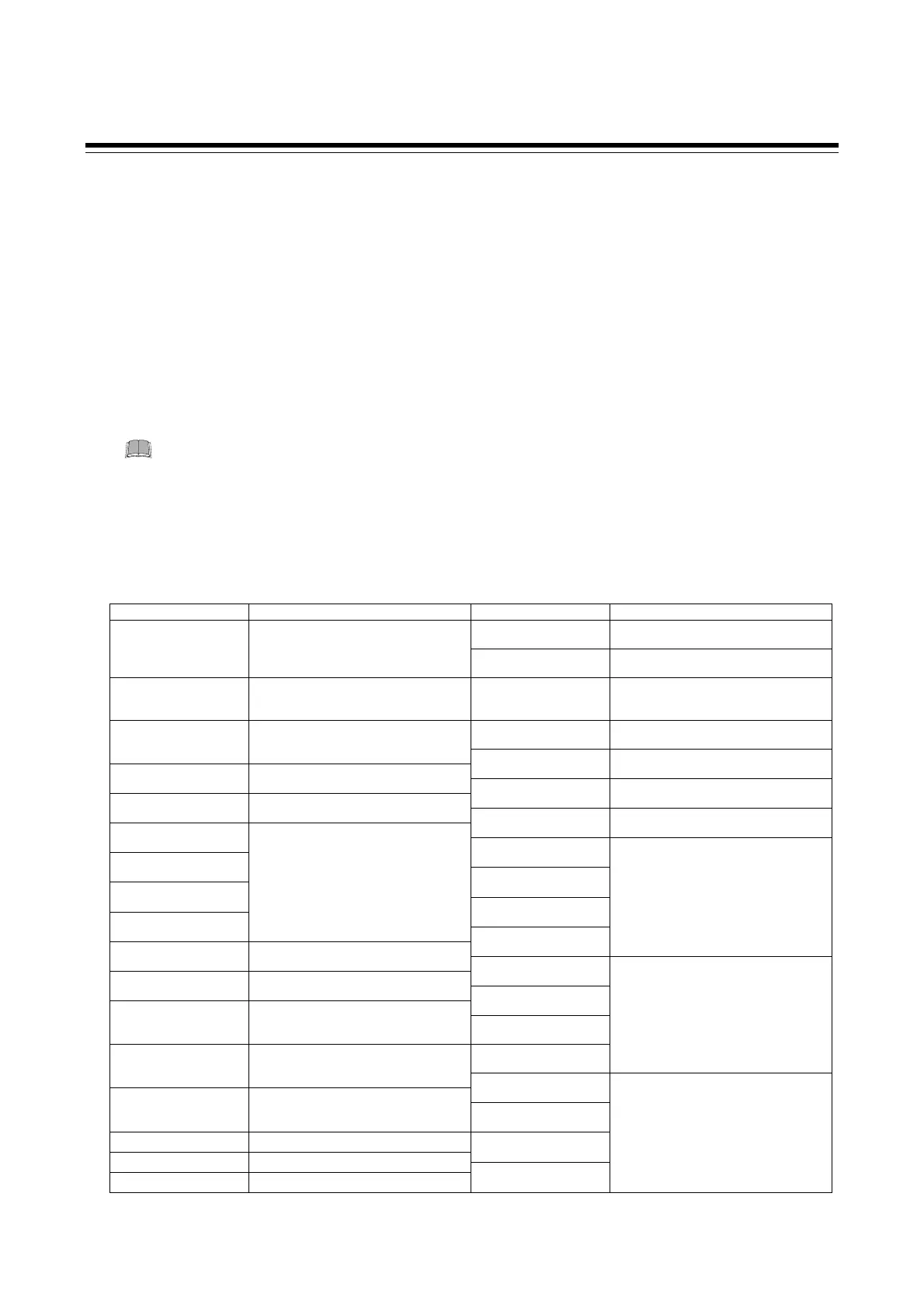
When Input type (INP) is changed
The following parameter will be changed to factory default values according to the new setting.
Item Default value Item Default value
Proportional band
[cool-side]
100 % of Proportional band [heat-side] Decimal point position TC/RTD inputs:
Without decimal point: 0
With decimal point: 1
Voltage (V)/Current (I) inputs: 1
Fine tuning setting
0
Input scale high TC/RTD inputs:
Maximum value of the selected input range
Voltage (V)/Current (I) inputs: 100.0
Overlap/Deadband TC/RTD inputs: 0 (0.0) °C [°F]
Voltage (V)/Current (I) inputs:
0.0 % of Input span
PV bias TC/RTD inputs: 0 (0.0) °C [°F]
Voltage (V)/Current (I) inputs: 0.0
Input scale low TC/RTD inputs:
Minimum value of the selected input range
Voltage (V)/Current (I) inputs: 0.0
PV digital filter 1
Setting limiter high Input scale high
Control loop break
alarm (LBA) time
480 seconds
Setting limiter low Input scale low
LBA deadband (LBD) 0
Set value 1 (SV1)
Event 1 set value (EV1)
Set value 2 (SV2)
Event 2 set value (EV2)
Set value 3 (SV3)
Event 3 set value (EV3)
Set value 4 (SV4)
TC/RTD inputs: 0 (0.0) °C [°F]
Voltage (V)/Current (I) inputs: 0.0
Event 4 set value (EV4)
TC/RTD inputs: 50 (50.0) °C [°F]
Voltage (V)/Current (I) inputs: 5.0
Setting change rate
limiter (up)
0 (0.0) °C [°F]
Event 1 set value (EV1)
[high]
Setting change rate
limiter (down)
0 (0.0) °C [°F]
Event 2 set value (EV2)
[high]
ON/OFF action
differential gap (upper)
TC/RTD inputs: 1 (1.0) °C [°F]
Voltage (V)/Current (I) inputs:
0.1 % of Input span
Event 3 set value (EV3)
[high]
Event 4 set value (EV4)
[high]
TC/RTD inputs: 50 (50.0) °C [°F]
Voltage (V)/Current (I) inputs: 5.0
ON/OFF action
differential gap (lower)
TC/RTD inputs: 1 (1.0) °C [°F]
Voltage (V)/Current (I) inputs:
0.1 % of Input span
Event 1 set value (EV1’)
[low]
Proportional band
[heat-side]
TC/RTD inputs: 30 (30.0) °C [°F]
Voltage (V)/Current (I) inputs:
3.0 % of Input span
Event 2 set value (EV2’)
[low]
Integral time 240 seconds Event 3 set value (EV3’)
[low]
Derivative time 60 seconds
Anti-reset windup (ARW) 100 % of Proportional band [heat-side]
Event 4 set value (EV4’)
[low]
TC/RTD inputs:
−50
(−50.0)
°C [°F]
Voltage (V)/Current (I) inputs: −5.0
Continued on the next page.

 Loading...


