3. WIRING
IMR02C15-E4
3-11
Digital output 1 to 4 (DO1 to DO4) [optional]
• Models that were specified with digital output when ordering can use the following terminal
numbers.
RB100: Terminal No. 7 to 9 (DO1, DO2)
RB700: Terminal No. 10 to 12 (DO1, DO2), Terminal No. 7 to 9 (DO3, DO4)
RB400/500/900: Terminal No. 7 to 9 (DO1, DO2), Terminal No. 19 to 21 (DO3, DO4)
• Output type is only relay contact output (2).
Relay contact output (2)
250 V AC 1A (Resistive load), 30 V DC 0.5 A (Resistive load), 1a contact
Electrical life: 150,000 times or more (Rated load)
• Output of the Event function can be allocated to DO1 to DO4.
• Outputs of DO1/DO2 and DO3/DO4 are isolated.
DO1 and DO2 or DO3 and DO4 use the same common terminal (RB100/400/500/900: No. 9 for
DO1/DO2, and No. 21 for DO3/DO4 RB700: No. 12 for DO1/DO2, and No. 9 for DO3/DO4)
and are not isolated.
• For RB400/500/700/900, the maximum number of digital outputs (DO) depends on output types of
OUT1 and OUT2. Refer to the “table of the maximum number of DO below.
M: Relay contact output (1) V: Voltage pulse output T: Triac output D: Open collector output
OUT2 (Including transmission output)
No OUT2
output
M, T, D
V
(Load: 10 mA)
V
(Load: 20 mA)
Current
output
Voltage
output
M, T, D
DO: 4 points DO: 4 points DO: 4 points DO: 4 points DO: 4 points DO: 4 points
V (Load: 10 mA)
DO: 4 points DO: 4 points DO: 4 points DO: 4 points
DO: 2 points DO: 2 points
V (Load: 20 mA)
DO: 4 points DO: 4 points DO: 4 points
DO: 2 points DO: 2 points DO: 2 points
Current output
DO: 4 points DO: 4 points
DO: 2 points DO: 2 points DO: 2 points DO: 2 points
OUT1 *
Voltage output
DO: 4 points DO: 4 points
DO: 2 points DO: 2 points DO: 2 points DO: 2 points
( : It represents selection of digital outputs DO3 and DO4 is not available.)
* When the instrument has two digital outputs (DO1 and DO2) and no OUT2 output, “V” type output (load: 40 mA) can be
specified for OUT1.
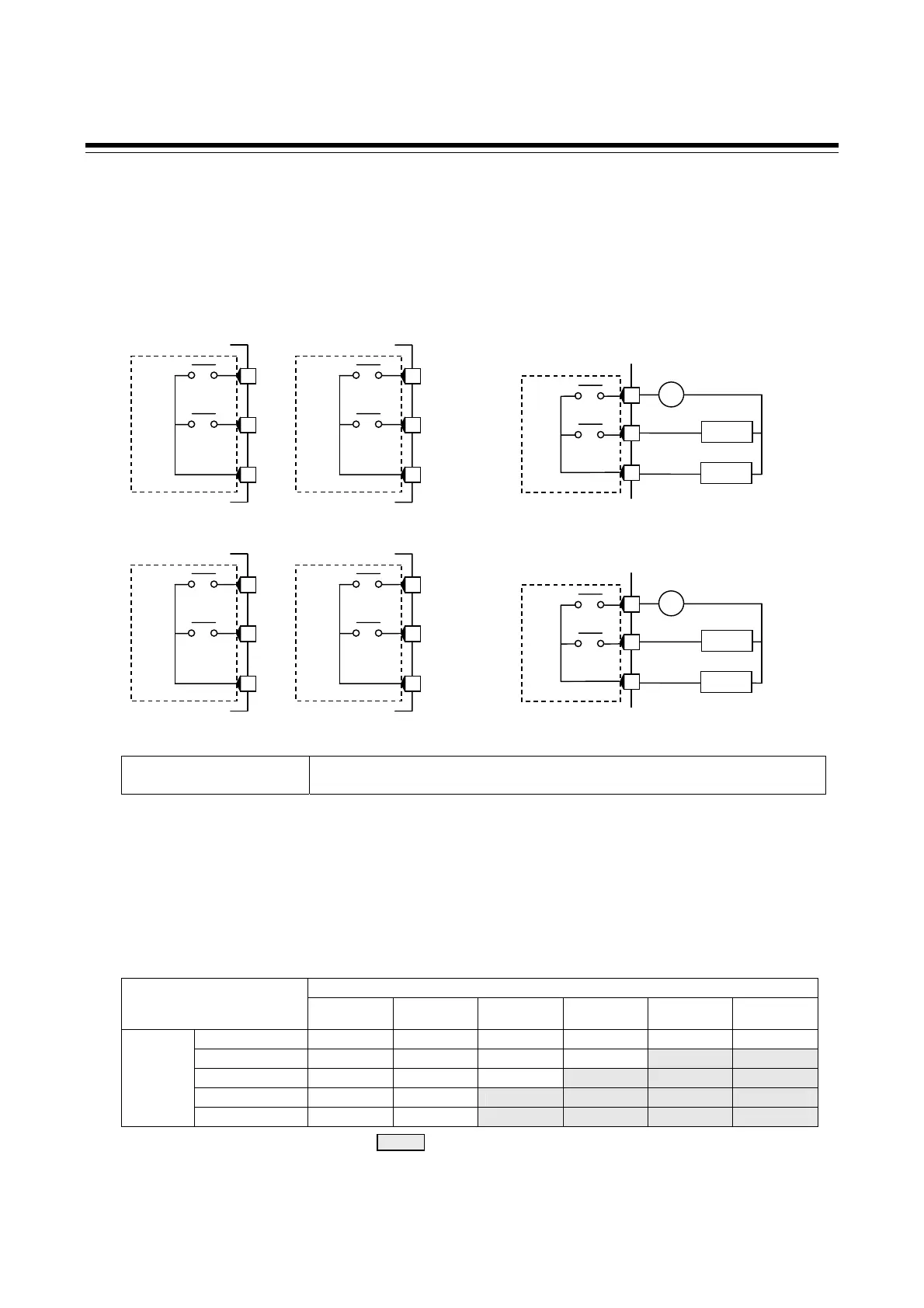
Wiring example
7
COM
9
DO1
NO
8
DO2
NO
Load
~
Load
•
8
7
9
DO2
DO1
NO
COM
NO
20
19
21
DO4
DO3
NO
COM
NO
Relay contact output (2)
Relay contact output (2)
RB100/400/500/900 RB400/500/900
Wiring example
10
COM
12
DO1
NO
11
DO2
NO
Load
~
Load
•
11
10
12
DO2
DO1
NO
COM
NO
8
7
9
DO4
DO3
NO
COM
NO
Relay contact output (2)
Relay contact output (2)
RB700
RB700

 Loading...


