APPENDIX
A-2 IMR02C15-E4
A.
Removing the Internal Assembly
Removing the internal assembly from the case is rarely required. Should you remove the internal
assembly without disconnecting the external wiring, take the following steps:
Apply pressure very carefully when removing internal assembly to avoid damage to the
frame.
To conform to IEC61010-1 requirements for protection from electric shock, the internal
assembly of this instrument can only be removed with an appropriate tool.
Procedures
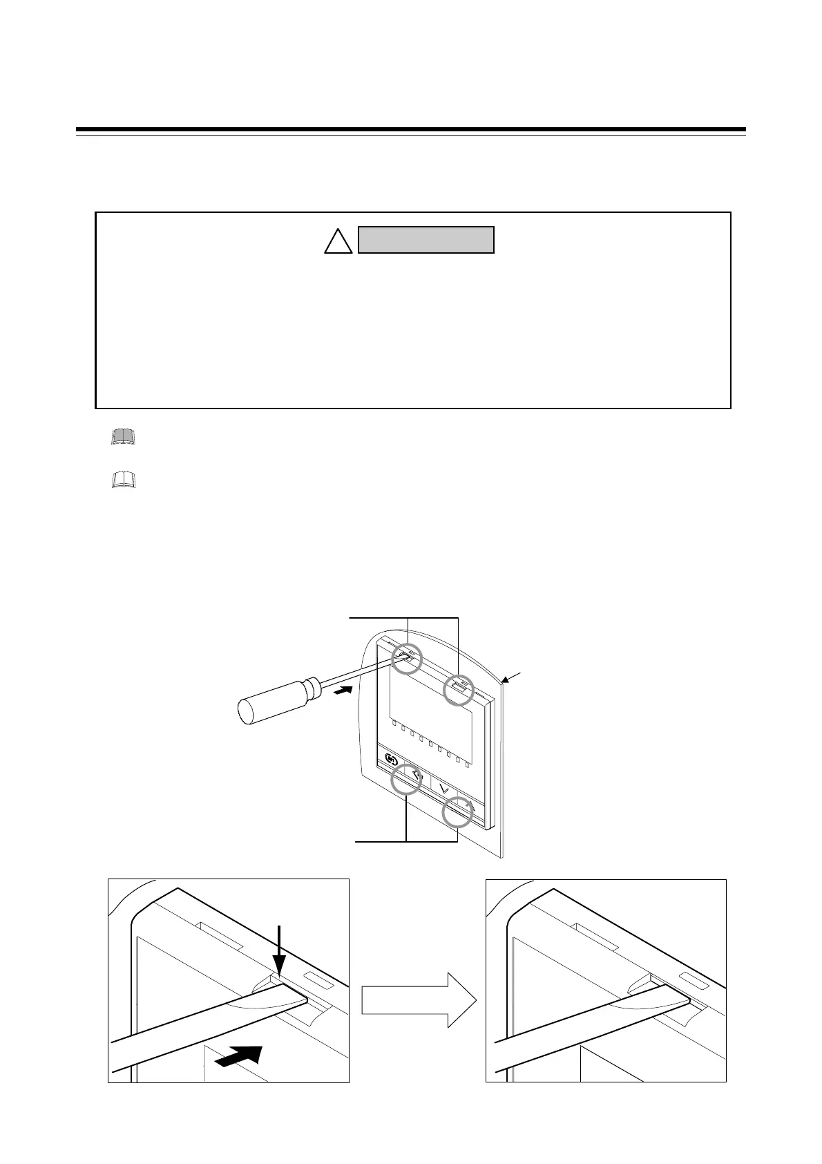
1. Insert the screwdriver in the plug-in lock section as shown in the following figure, and then lightly
push the screwdriver in the horizontal direction to release the plug-in lock released bar.
The plug-in lock section is released.
Plug-in lock
released bar
ロック解除バーを押す
Plug-in lock section
release status
To prevent electric shock or instrument failure, only qualified personnel
should be allowed to pull out the internal assembly.
To prevent electric shock or instrument failure, always turn off the power
before pulling out the internal assembly.
To prevent injury or instrument failure, do not touch the internal printed wiring
board.
WARNING
!
Recommended tool: Slotted screwdriver
Tip width: 6 mm or less
* The number of plug in lock sections of
RB100/400/700 (at top and bottom sides)
[RB500 (at right and left side)]:
E
h
n
ti
n
Panel
Plug-in lock section
(Upper: 2 places) *
Plug-in lock section
Lower: 2
laces
*

 Loading...


