4. BASIC OPERATION
4-2 IMR02C15-E4
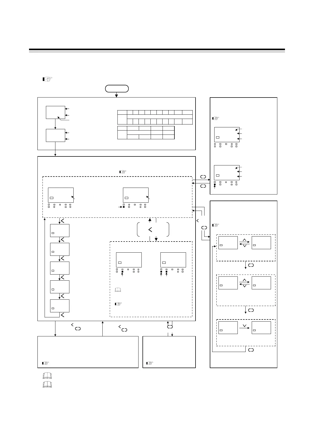
4.1 Operation Menu
The controller has five different modes. All settable parameters belong to one of them.
The following chart show how to access different setting mode.
For the details of changing set value, refer to 4.2 Changing Set Value (P. 4-4).
Power ON
Monitor Display Mode
INP$
@C0K
1372$
-200
Symbol
Unit for input and SV display
TC/RTD input:
°
C or
°
F
Voltage/Current input: No display
Automatically
(in 2 sec.)
Input range high *
Input range low *
Input type symbol
* When sensor type is K thermocouple
(
−
200 to
+
1372
°
C)
Input type/Input range Display
Symbol
K J T S R E B N P W
TC
Input
type
KJTSREBNPL
Ⅱ
W5Re
W26Re
Symbol
PT JP V I
RTD Voltage Current
Input
type
Pt100 JPt100
V mA
Automatically
(in 2 sec.)
CT1
$
0.0
SV1
Current transformer 1
(CT1) input value
monitor
CT2
$
0.0
SV1
MV%
-05.0
SV1
MV2
%
-05.0
SV1
TIME$
0:00
SV1
AUTO mode
28
0
SV1
OUT1
OUT
T
DO1 DO2
MA
STOP
DO3
DO4
PV/SV monitor
Unit of PV *
* TC/RTD input:
°
C or
°
F
Voltage/Current input: No display
28
0.0
SV1
OUT1
OUT
T
DO1 DO2
MA
STOP
DO3
DO4
(MAN mode)
PV/SV monitor
Unit of PV *
MAN lamp lights
[RUN mode (factory shipment)]
Current transformer 2
(CT2) input value
monitor
Manipulated output
value (MV1) monitor
[heat-side]
Manipulated output
value (MV2) monitor
[cool-side]
Remaining time
monitor
R/S
R/S
R/S
R/S
R/S
R/S
28
STOP
SV1
OUT1
OUT
T
DO1 DO
MA
STOP
DO3
DO4
[STOP mode (factory shipment)]
28
STOP
SV1
OUT1
OUT
T
DO1 DO2
MA
STOP
DO3
DO4
(AUTO mode) (MAN mode)
MAN lamp
lights
STOP lamp
lights
STOP lamp
lights
R/S
RUN/STOP transfer
(2 seconds or more)
Even in the STOP state the Set value (SV)
and the Parameter setting mode can be set,
and Mode switching is possible.
Refer to 6.1 RUN/STOP Transfe
for the
state of the controller in STOP mode (P. 6-2).
In this mode, it is possible to set operating conditions such as
the Set lock level, Mode switching, the non-display selection o
Parameter setting mode (F01 to F10), etc. specific to each
customer.
Refer to 8.5 Engineering Mode (P. 8-43).
Engineering Mode Parameter Setting Mode
Change parameters related to
control such as PID values.
Refer to P. 4-3, P. 8-12.
SV Setting Mode
In this mode, control Set value (SV) and
Manual output value (MV) in Manual (MAN)
mode can be set.
(AUTO mode)
28
0000
SV1
OUT1
OUT
T
DO1 DO2
MA
STOP
DO3
DO4
PV
Unit of SV *
SV can be changed
[Flashing]
* TC/RTD input: °C or °F
Voltage/Current input: No display
28
000.0
SV1
OUT1
OUT
T
DO1 DO2
MA
STOP
DO3
DO4
(MAN mode)
PV
Unit of MV: %
MV can be changed
[Flashing]
MAN lamp lights
Refer to
8.2 SV Setting Mode (P. 8-6)
.
Refer to
8.1 Monitor Display Mode (P. 8-2)
.
SET
SET
SET
Mode Switching
In this mode,
uto/Manual transfer, Set
data unlock/lock transfer, and Interlock
release can be performed.
Auto (AUTO)/Manual (MAN) transfer
AUTO$
0000
SV1
Auto (AUTO)
MAN$
0001
SV1
Manual (MAN)
[Factory shipment: AUTO mode]
Set data unlock/lock transfer
ILR
$
0001
SV1
Interlock state
ILR
$
0000
SV1
Interlock release
[Factory shipment: Interlock function OFF]*
Interlock release
SET
ULCK
$
0000
SV1
Unlock
LCK
$
0001!
SV1
Lock
[Factory shipment: Data lock function OFF
(All parameters can be changed)]*
* The setting to enable the function is
configured in Engineering mode.
Refer to
8.3 Mode Switching (P. 8-9)
.
SET
(2 seconds or more)
SET
Press the
while
pressing
the
SET
R/S
Press the while
pressing the
SET
R/S
Press the while
pressing the
for 4 seconds
SET
R/S
− Monitor parameters such as PV, SV and MV.
−
Conduct operation in this mode.
Display returns to the PV/SV monitor if no key operation is performed within 1 minute.
If any item not described in the specification or the relevant function is not selected, there
may be parameters which are not displayed.

 Loading...


