5. SETUP PROCEDURES PRIOR TO RUNNING THE INSTRUMENT
IMR02C15-E4 5-3
5.1 Initial Setting
Check the parameter related to the input
Parameter settings related to the control input specifications such as the input type, can be checked in
Engineering mode. Parameters which are not specified when ordering must be set before use.
For input types, refer to Input type (P. 8-88).
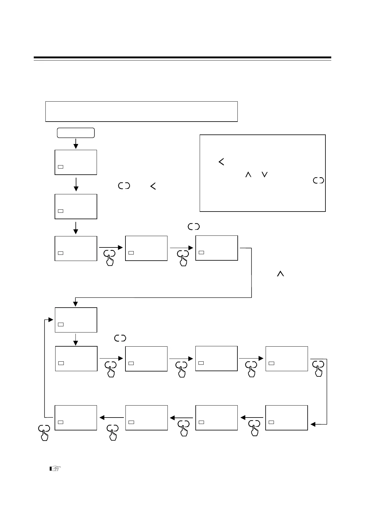
Power ON
PV/SV monitor
28
0
SV1
F00.
SV1
F21.
SV1
INP
0000
SV1
MOdE
0128
SV1
Check the Input type.
0000: Thermocouple (K)
–199.9 to +400.0 °C
Setup example:
Input specification: Thermocouple (K) 0 to 400 °C [Input range code: K02]
PGDP
0000
SV1
BOS
0000
SV1
PGSH
0400
SV1
PGSL
0000
SV1
SLH
0400
SV1
SLL
0000
SV1
DSOP
0000
SV1
F21.is a parameter group
related to input.
Check the Decimal point
position.
0000: No decimal place
Select the Burnout
direction.
0000: Upscale
0001: Downscale
Check the Input scale
high.
0400: 400 °C
Check the Input scale low.
0000: 0 °C
Check the Setting limiter
high.
0400: 400 °C
Check the Setting limite
low.
0000: 0 °C
Select the PV flashing
display at input error.
0000: Flashing
0001: Non-flashing display
SET
SET
SET
SET
SET
SET
SET
SET
To display after F21.
change the set value
from 0000 to 0128.
R/S
0001
SV1
F00.
SV1
SET
SET
To enable settings after
F21.change the set value
from 0000 (RUN) to 0001
(STOP).
Set value change and registration
• The blinking digit indicates which digit can be
set. The blinking digit can be moved by pressing
the key.
•
However, the changed data is not stored by the
operation of the and keys alone. In order
for the new parameter value to be stored, the
key must be pressed within 1 minute after the
new value is displayed. The new value will then
be saved and the display will move to the next
parameter.
R/S
SET
Press the key to F21.
Press the key
SET
Go to Engineering mode by pressing and
holding the key and keys for
4 seconds or more.
R/S
SET
Switch to the ModE screen by pressing the key three times.
SET

 Loading...


