Publication 1734-UM001D-EN-P - April 2008
106 POINT I/O Module Data
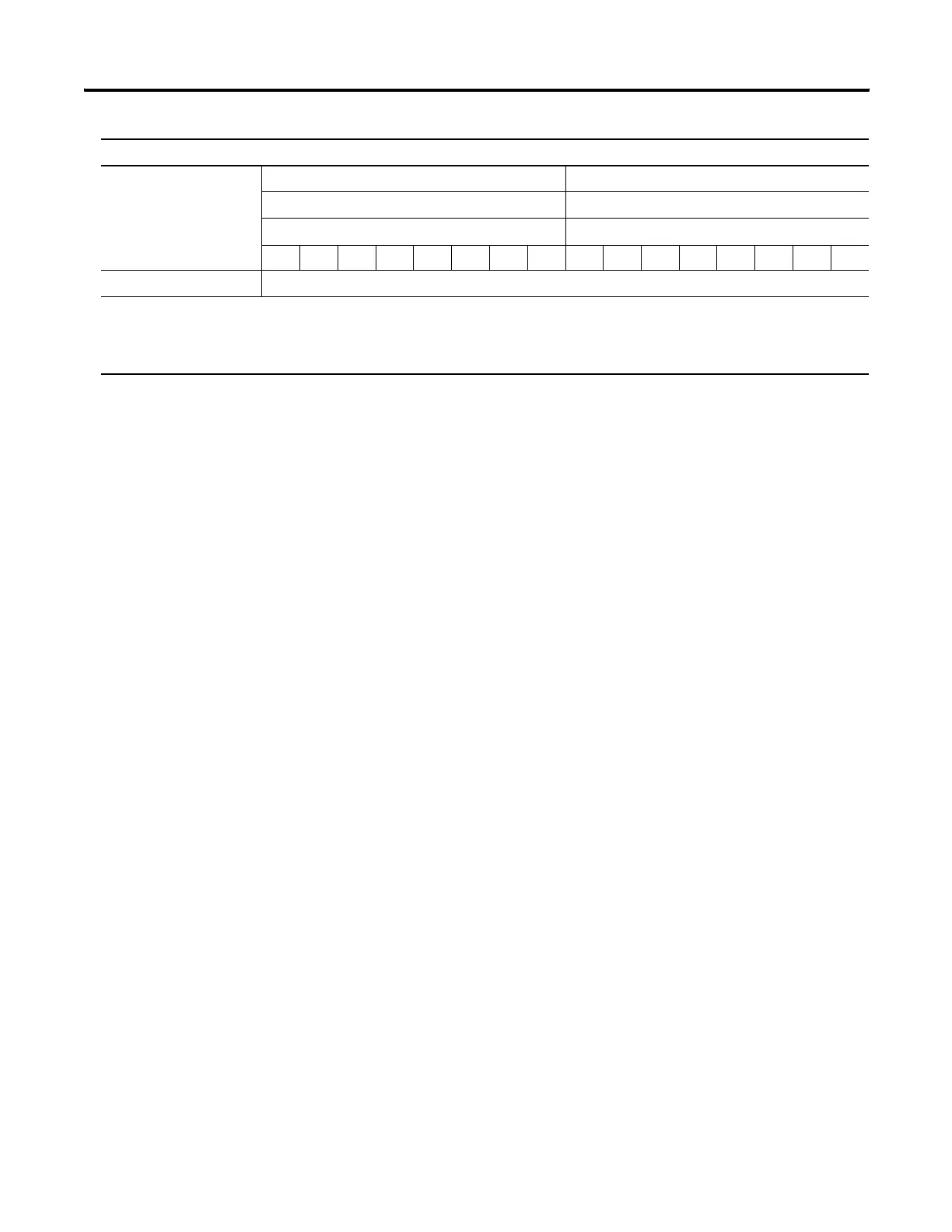
Produces (scanner Rx) Input Channel 0 - High Byte Input Channel 0 - Low Byte
Input Channel 1 - High Byte Input Channel 1 - Low Byte
Status Byte for Channel 1 Status Byte for Channel 0
OR UR HHA LLA HA LA CM CF OR UR HHA LLA HA LA CM CF
Consumes (scanner Tx) No consumed data
Where: CF = Channel Fault status; 0 = no error, 1 = fault CM = Calibration Mode; 0 = normal, 1 = calibration mode
LA = Low Alarm; 0 = no error, 1 = fault HA = High Alarm; 0 = no error, 1 = fault
LLA = Low/Low Alarm; 0 = no error, 1 = fault HHA = High/High Alarm; 0 = no error, 1 = fault
UR = Underrange; 0 = no error, 1 = fault OR = Overrange; 0 = no error, 1 = fault
Default Data Map for the 1734-IE2V Analog Input Module
 Loading...