Publication 1734-UM001D-EN-P - April 2008
Install POINTBlock I/O Modules 87
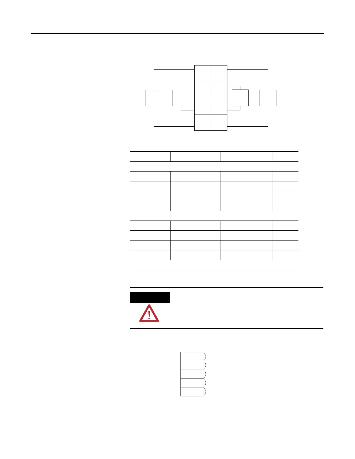
Output Wiring Diagram
DeviceNet Connector Wiring
Output Terminal Common Terminal Power
Remote Termination Block 3
Channel 0 0 6
Channel 1 1 7
Channel 2 2 4
Channel 3 3 5
Remote Termination Block 4
Channel 4 0 6
Channel 5 1 7
Channel 6 2 4
Channel 7 3 5
Module power is supplied from the internal power bus.
ATTENTION
When connecting more then one wire in a termination point,
make sure that both wires are the same gauge and type.
Load
In 0 In 1
In 2
L2
L2
L2
L2
In 3
Load
41967ac
L1 = 120V ac
3
5
7
01
2
4
6
Load
Load
DeviceNet
Connection
Red
White
Bare
Blue
Black
-V
42132
+V
CAN - High
Shield
CAN - Low
 Loading...