Publication 1734-UM001D-EN-P - April 2008
174 Default Data Maps
1734-OX2 Relay Output Module
Message Size: 1 Byte
Analog Module Default
Data Maps
I/O messages are sent to (consumed) and received from (produced) the
POINT I/O modules. You map these messages into the processor memory.
1734-IE2C Analog Current Input Module
Message Size: 6 Bytes
Channel Status
76543 2 1 0
Consumes (scanner Tx) Not used Ch1 Ch0 Channel state
Where: 0 = NO contact Off, NC contact On
1 = NO contact On, NC contact Off
15 14 13 12 11 10 09 08 07 06 05 04 03 02 01 00
Produces (scanner Rx) Input Channel 0 High Byte Input Channel 0 Low Byte
Input Channel 1 High Byte Input Channel 1 Low Byte
Status Byte for Channel 1 Status Byte for Channel 0
OR UR HHA LLA HA LA CM CF OR UR HHA LLA HA LA CM CF
Consumes (scanner Tx) No consumed data
Where:CF = Channel Fault status0 = no error1 = fault
CM = Calibration Mode 0 = normal1 = calibration mode
LA = Low Alarm 0 = no error1 = fault
HA = High Alarm 0 = no error1 = fault
LLA = Low/Low Alarm 0 = no error1 = fault
HHA = High/High Alarm 0 = no error1 = fault
UN = Underrange 0 = no error1 = fault
OR = Overrange 0 = no error1 = fault
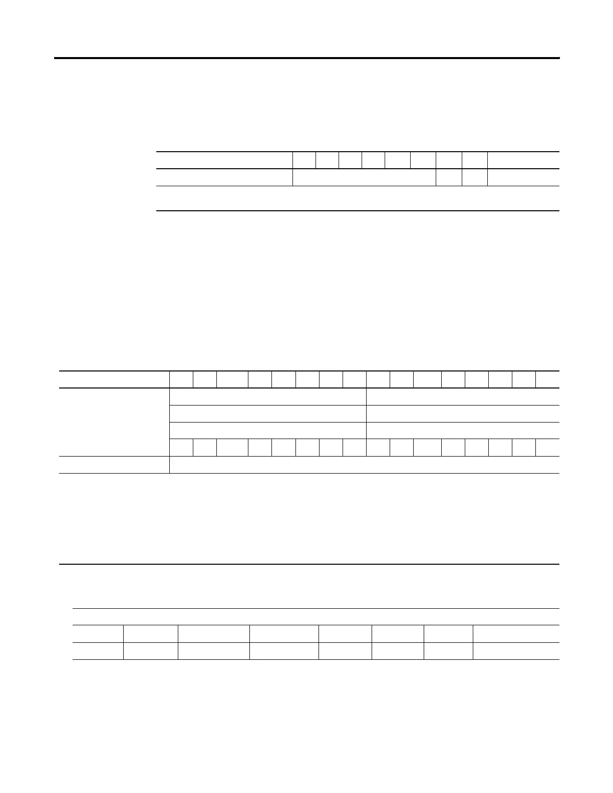
Channel Status Bytes
Bit 7 Bit 6 Bit 5 Bit 4 Bit 3 Bit 2 Bit 1 Bit 0
Over Range Under Range High High Alarm Low Low Alarm High Alarm Low Alarm CAL Mode Channel Fault
 Loading...