141 Publication 1734-UM001D-EN-P - April 2008
Chapter
6
Troubleshoot with the Indicators
About This Chapter
Read this chapter for information about troubleshooting with the following
indicators:
• Module status
• Network status
• Power indication
• Calibration status
• I/O POINT status (ON/OFF/fault or diagnostic)
Refer to each module’s individual indicators for detailed information.
About Module Diagnostics
All status and diagnostic information (strobed, polled, cyclic, or
change-of-state) is reported back over the network communication adapter. A
single point of failure is detected and reported at the module and to the
control system.
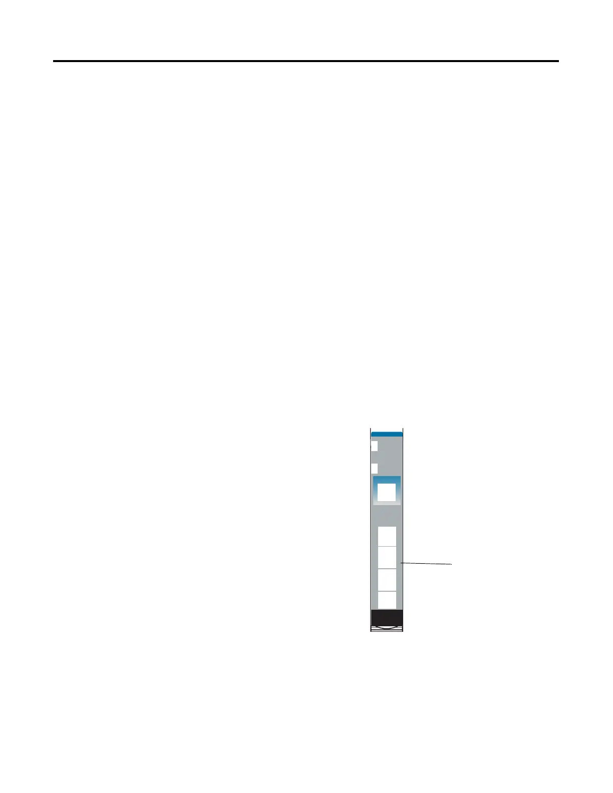
24VDC
Sink
Input
Module
Status
Network
Status
1734
IB4
NODE:
0
1
2
3
Node-level Diagnostics:
Point-level Diagnostics:
• Module Status Indicator
indicates the health of the
module
• Network Status Indicator
indicates the health of the
POINTBus or backplane
• I/O Point Indicator
indicates I/O (ON/OFF or
fault/diagnostic) status
• Digital outputs
Short circuit for ON-state
Open circuit for OFF-state
• Analog I/O
Loss of field power
Open wire
Calibration status
I/O Channel Status
Module Status
Network Status
42011
 Loading...