Publication 1734-UM001D-EN-P - April 2008
42 Install POINT I/O Modules
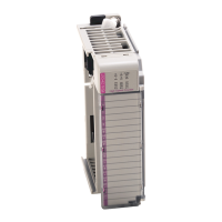
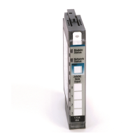
1734-OW2 and 1734-OW4 Relay Output Modules
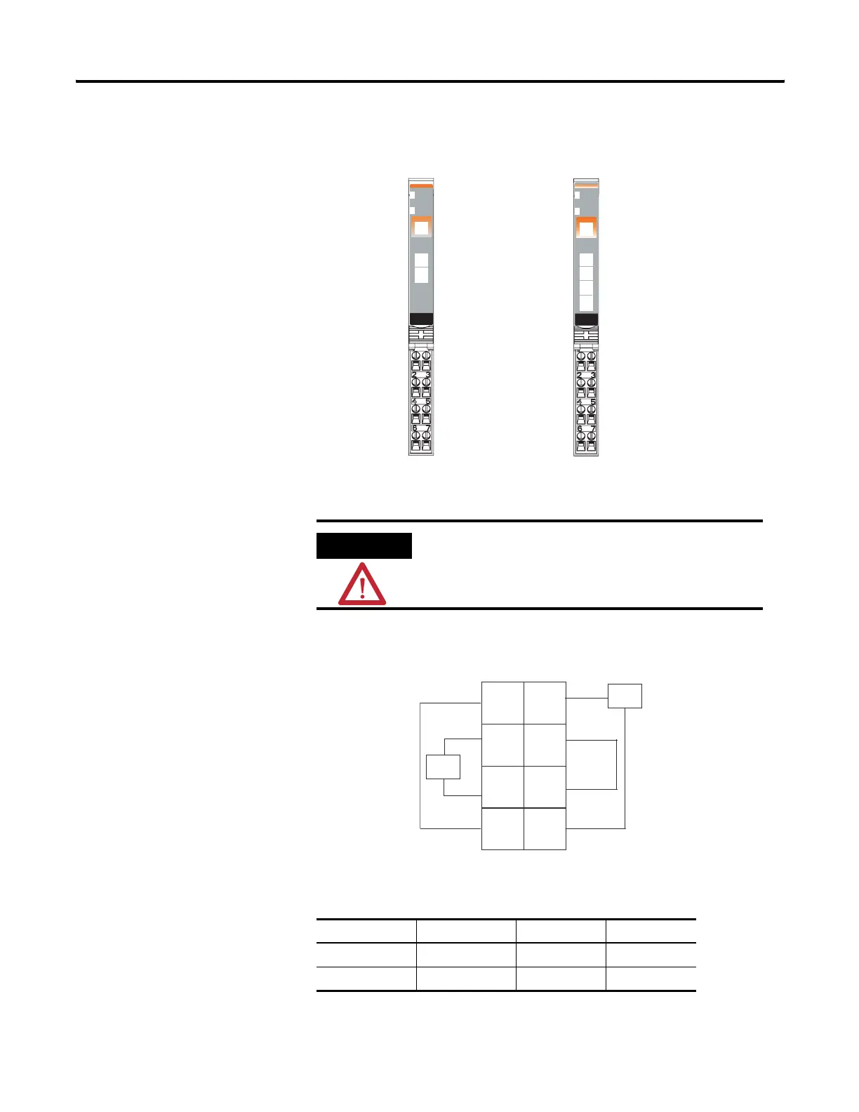
1734-OW2 Modules with Load Powered by Internal Power Bus
Wiring Diagram
ATTENTION
Relay contacts are not powered by the internal power bus.
Load power can be provided by the internal power bus or
an external power source.
Channel Output Common Supply
0A 0 4 6
0B 2 4 6
Relay
Output
Module
Status
Network
Status
1734
OW2
NODE:
0
1
41974
Module Status
Network Status
Status of Output 0
Status of Output 1
C
V
C
V
C = Common
V = Supply
Output 0A
Output 0B
Output 1A
Output 1B
Status of Output 2
Status of Output 3
Output 0A
Output 0B
Output 1A
Output 1B
Output 2A
Output 2B
Output 3A
Output 3B
Relay
Output
Module
Status
Network
Status
1734
OW4
NODE:
0
1
2
3
1734-OW2
1734-OW4
C
C
V
V
Out = Output channel relay contacts
V = Supply (can range from +5V dc…240V ac)
44340
Out 0A
Out 0B
Out 1A
Out 1B
Load
Load
0
2
4
6
3
5
7
1
 Loading...