Publication 1734-UM001D-EN-P - April 2008
Install POINTBlock I/O Modules 91
DeviceNet Connector Wiring
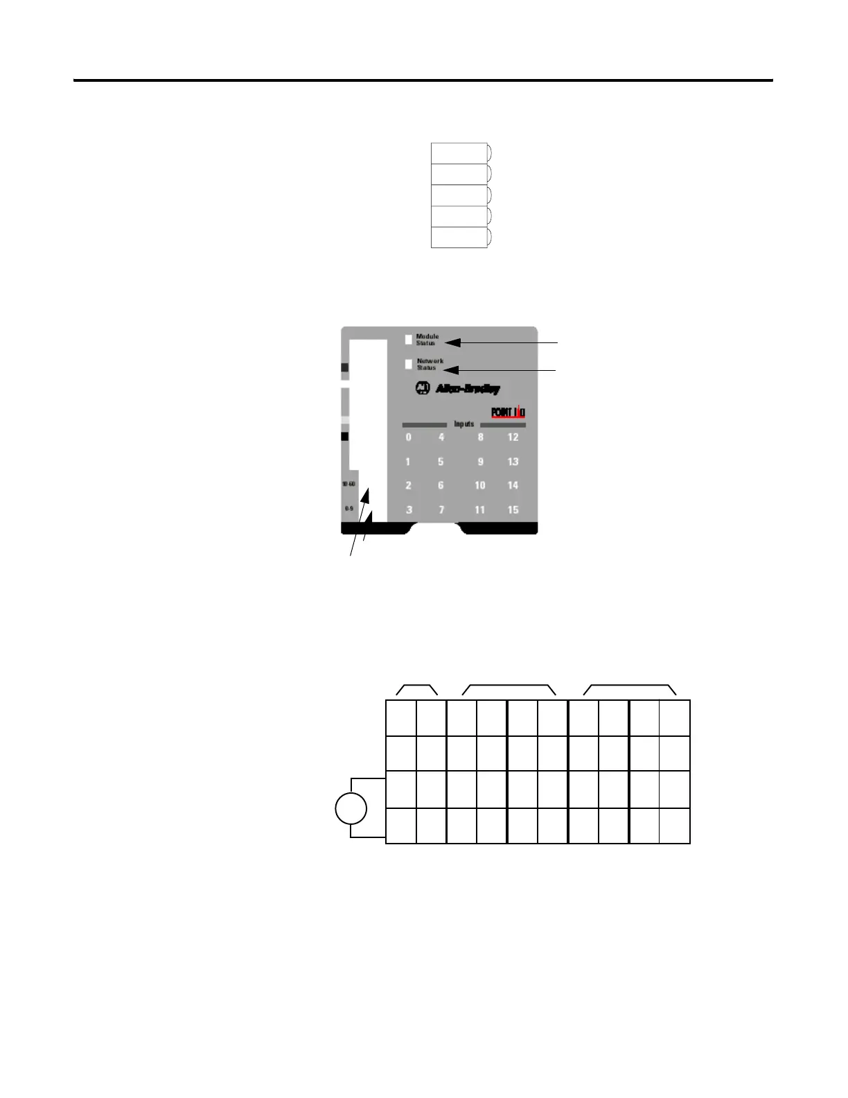
1734D-IA16 POINTBlock 16 ac Input Modules
Wire the 16 ac Input Module Wiring Diagram
DeviceNet
Connection
Red
White
Bare
Blue
Black
-V
42132
+V
CAN - High
Shield
CAN - Low
42004
10’s Node Address Rotary Switch
1’s Node Address Rotary Switch
Module Status
Network Status
I/O Status
V ac
NC
NC
L2in
L1in
120V ac
Power
NC = No Connection Chas Gnd = Chassis Ground
L2/N = AC Return/Neutral L1 = AC Power
42064IB
NC
NC
0
2
L2
L1
1
3
L2
L1
4
6
L2
L1
5
7
L2
L1
8
10
L2
L1
9
11
L2
L1
12
14
L2
L1
13
15
L2
L1
Field Power
Inputs
L1in
L2in
This supply will be connected to the internal power bus.
RTB 0 RTB 1 RTB 2 RTB 3 RTB 4
01
23
45
67
01
23
45
67
01
23
45
67
01
23
45
67
01
23
45
67
 Loading...