Publication 1734-UM001D-EN-P - April 2008
78 Install POINTBlock I/O Modules
Wiring POINTBlock
Modules
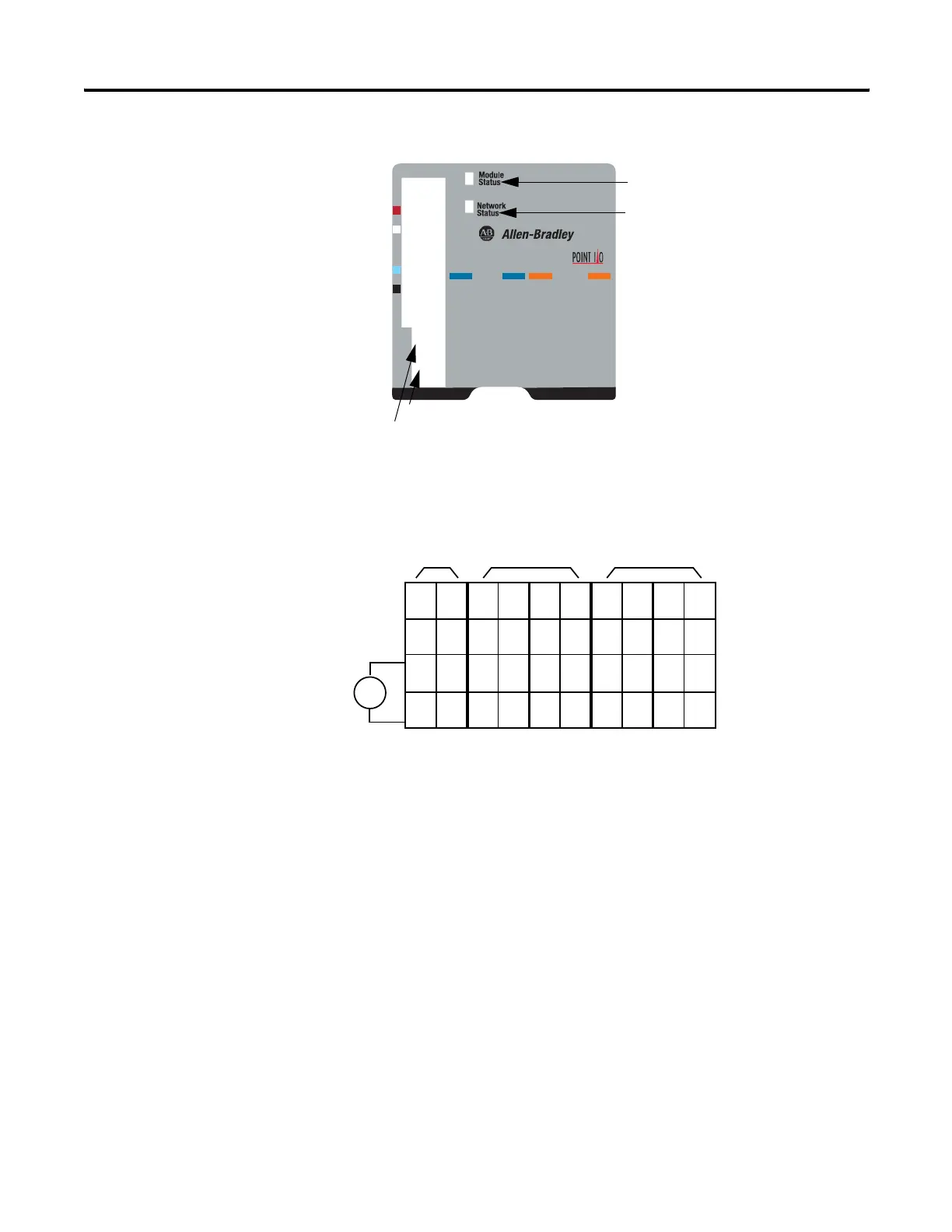
1734D-IB8XOB8 POINTBlock 8 dc In/8 dc Out Modules
8 Input/8 Output Module Wiring Diagram
0
1
2
3
4
5
6
7
0
1
2
3
4
5
6
7
0-9
10-60
Inputs
Outputs
42004
10’s Node Address Rotary Switch
1’s Node Address Rotary Switch
Module Status
Network Status
I/O status
V dc
NC
NC
Cin
Vin
12/24V dc
Power
NC = No Connection Chas Gnd = Chassis Ground
C = Common V = Supply
42064
NC
NC
Cin
Vin
0
2
C
V
1
3
C
V
4
6
C
V
5
7
C
V
0
2
C
C
1
3
C
C
4
6
C
C
5
7
C
C
Field
Power
Inputs Outputs
This supply will be connected to the internal power bus.
01
23
45
67
01
23
45
67
01
23
45
67
01
23
45
67
01
23
45
67
RTB 0 RTB 1 RTB 2 RTB 3 RTB 4
 Loading...