Publication 1734-UM001D-EN-P - April 2008
50 Install POINT I/O Modules
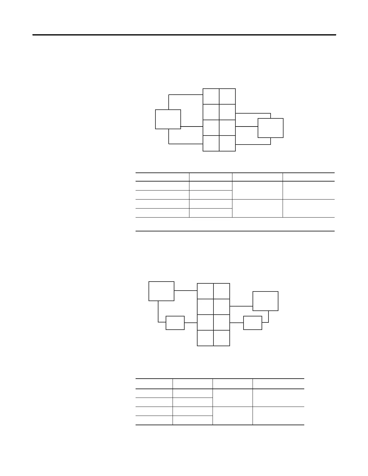
734-OX2 Module with Load Powered by Internal Power Bus
Wiring Diagram
1734-OX2 Modules with Load Powered by External Power Bus
Wiring Diagram
Channel Output Relay Common Supply
0 (N.C.) 0 4 6
0 (N.O.) 2
1 (N.C.) 1 5 7
1 (N.O.) 3
Supply voltage can range from +5V dc…240V ac, depending on relay load.
12V, 24V dc, 120V, 240V ac power for the module is provided by the internal power bus.
Channel Output Relay Common
Supply
1(1)
(1)
Supply voltage can range from +5V dc…240V ac, depending on relay load. 12V, 24V dc,
120V, 240V ac power for the module is provided by the internal power bus
0 (N.C.) 0
46
0 (N.O.) 2
1 (N.C.) 1
57
1 (N.O.) 3
+V
+V
42019OX
Out 0
NC
Out 1
NC
Load
Load
0
2
4
6
3
5
7
1
L1
L1
NC = Normally closed
NO = Normally open
RC = Relay Common
+V = Positive Supply
L2/N
L2/N
Out 0
NO
Out 1
NO
Out 0
RC
Out 1
RC
+V
+V
Out 0
NC
Out 1
NC
Out 1
NO
Load
Power
Out = Output channel relay contacts
Power Supply = can range from +5V dc…240V ac
RC = Relay Common
0
2
4
6
3
5
7
1
Power
Supply
Load
L1
L2/N
L1
L2/N
42014OX
Out 1
RC
Out 0
RC
Out 0
NO
 Loading...