Publication 1734-UM001D-EN-P - April 2008
Install POINTBlock I/O Modules 95
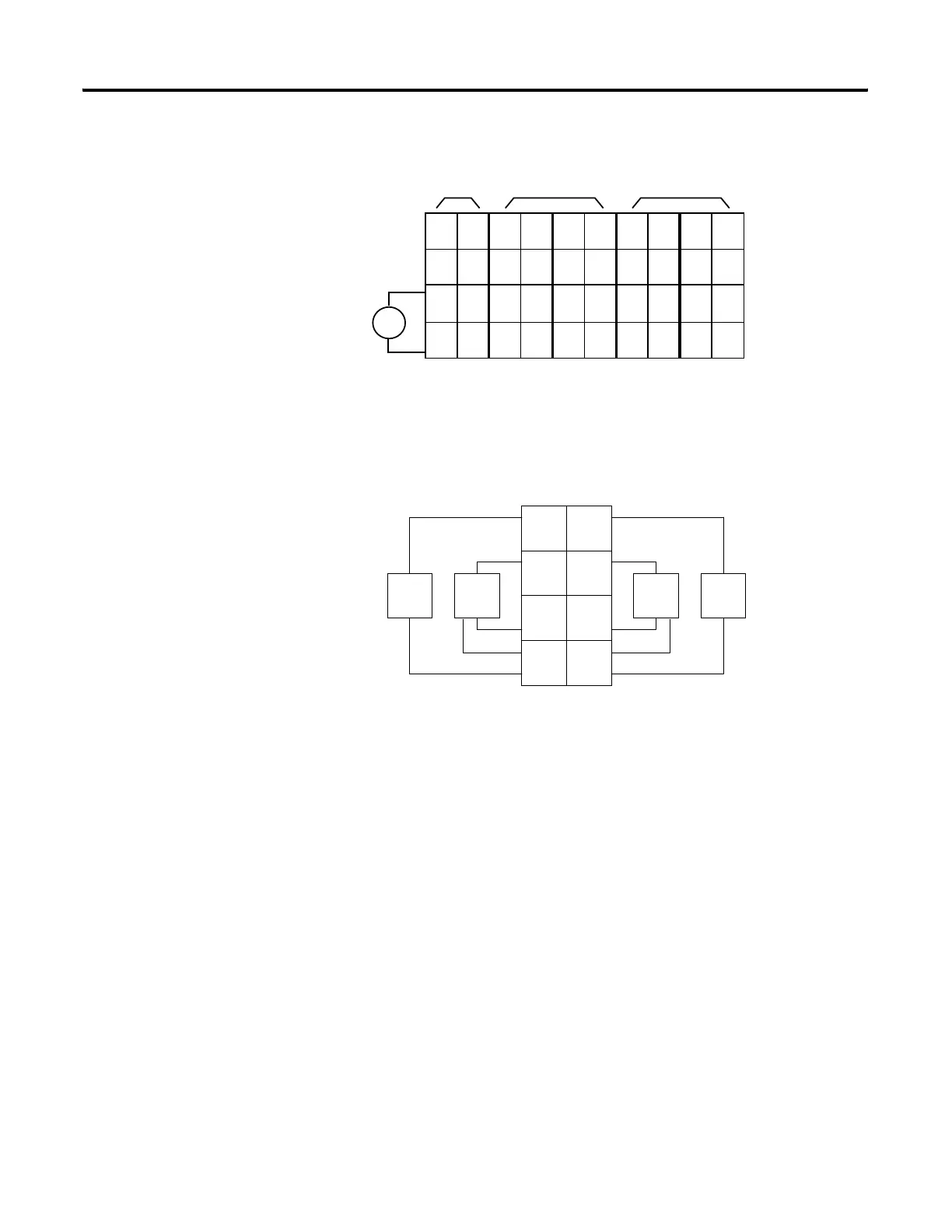
16 dc Input Module Wiring Diagram
Sink Input Wiring Diagram
V dc
NC
NC
Cin
Vin
12/24V dc
42064
NC
NC
Cin
Vin
0
2
C
V
1
3
C
V
4
6
C
V
5
7
C
V
8
10
C
V
9
11
C
V
12
14
C
V
13
15
C
V
Field
Power
Inputs
This supply will be connected to the internal power bus.
01
23
45
67
01
23
45
67
01
23
45
67
01
23
45
67
01
23
45
67
RTB 0 RTB 1 RTB 2 RTB 3 RTB 4
NC =
No Connection
C = Common
Chas Gnd =
Chassis Ground
V = Supply
Prox
In 0 In 1
In 2
C
VV
C
In 3
Prox ProxProx
41967
V = 12/24V dc
C = Common
3
5
7
01
2
4
6
3-wire2-wire
RTB 1
Repeat for RTB 2, RTB 3 and RTB 4.
 Loading...