Publication 1734-UM001D-EN-P - April 2008
112 POINT I/O Module Data
The 1734-OE2V module:
• consumes 4 bytes of data (scanner Rx) in this format:
– Channel 0 Data (2 bytes)
– Channel 1 Data (2 bytes)
• produces 2 bytes of data (scanner Tx) in this format:
– Channel 0 Status (1 byte)
– Channel 1 Status (1 byte)
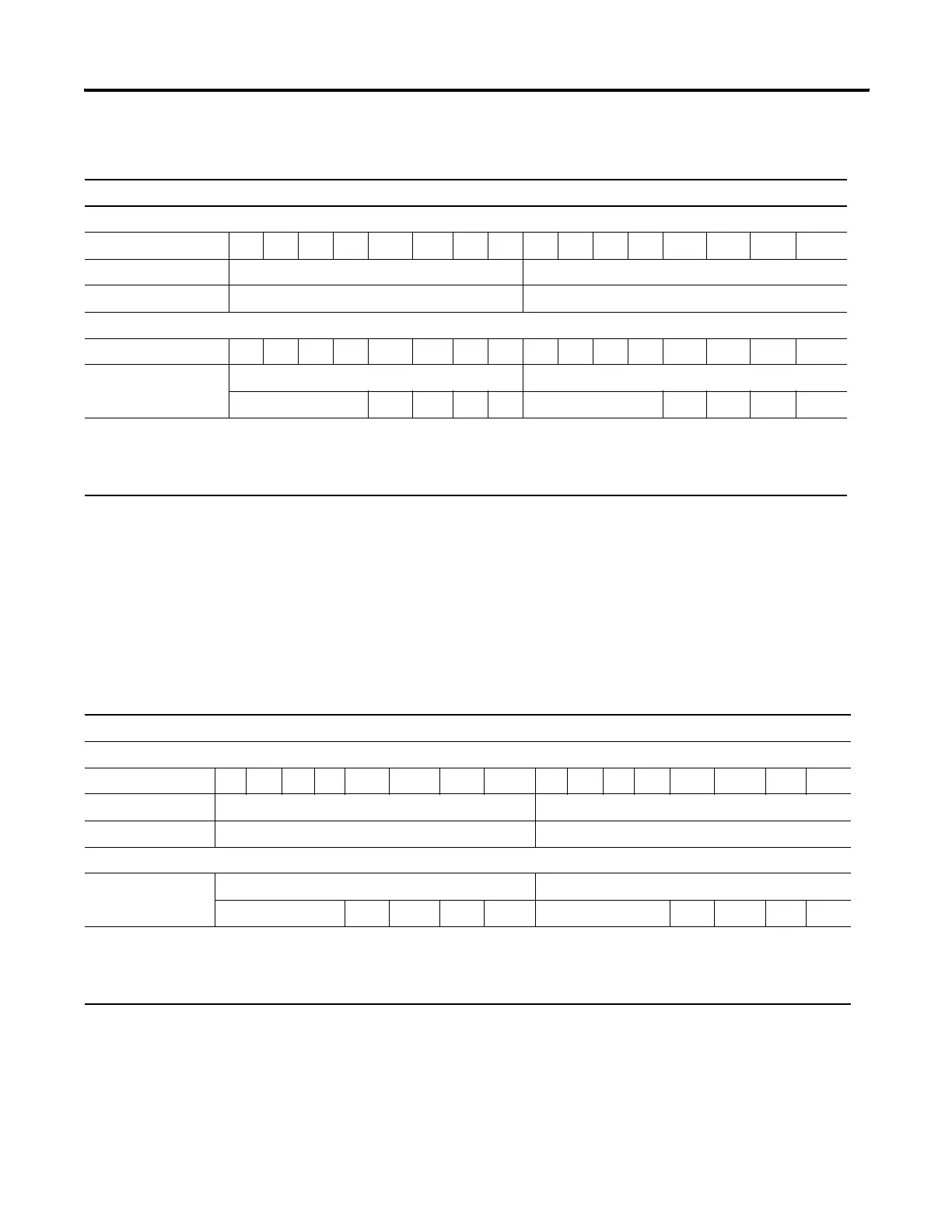
Default Data Map for the 1734-OE2C Analog Output Module
Message Size: 4 Bytes
15 14 13 12 11 10 09 08 07 06 05 04 03 02 01 00
Consumes (Tx) Output Channel 0 High Byte Output Channel 0 Low Byte
Output Channel 1 High Byte Output Channel 1 Low Byte
Message Size: 2 Bytes
15 14 13 12 11 10 09 08 07 06 05 04 03 02 01 00
Produces (Rx) High Byte - Channel 1 Status Low Byte - Channel 0 Status
Not used HCA LCA CM CF Not used HCA LCA CM CF
Where: CF = Channel Fault status; 0 = no error, 1 = fault
CM = Calibration Mode; 0 = normal, 1 = calibration mode
LCA = Low Clamp Alarm; 0 = no error, 1 = fault
HCA = High Clamp Alarm; 0 = no error, 1 = fault
Default Data Map for the 1734-OE2V Analog Output Module
Message Size: 4 bytes
15 14 13 12 11 10 09 08 07 06 05 04 03 02 01 00
Consumes (Tx) Output Channel 0 High Byte Output Channel 0 Low Byte
Output Channel 1 High Byte Output Channel 1 Low Byte
Message Size: 2 Bytes
Produces (Rx) High Byte - Channel 1 Status Low Byte - Channel 0 Status
Not used HCA LCA CM CF Not used HCA LCA CM CF
Where: CF = Channel Fault status; 0 = no error, 1 = fault
CM = Calibration Mode; 0 = normal, 1 = calibration mode
LCA = Low Clamp Alarm; 0 = no error, 1 = fault
HCA = High Clamp Alarm; 0 = no error, 1 = fault
 Loading...