Publication 1734-UM001D-EN-P - April 2008
Install POINT I/O Modules 25
To install the mounting base assembly on the DIN rail, proceed as follows.
1. Position the mounting base (wiring base assembly) vertically above the
installed units (adapter, power supply, or existing module).
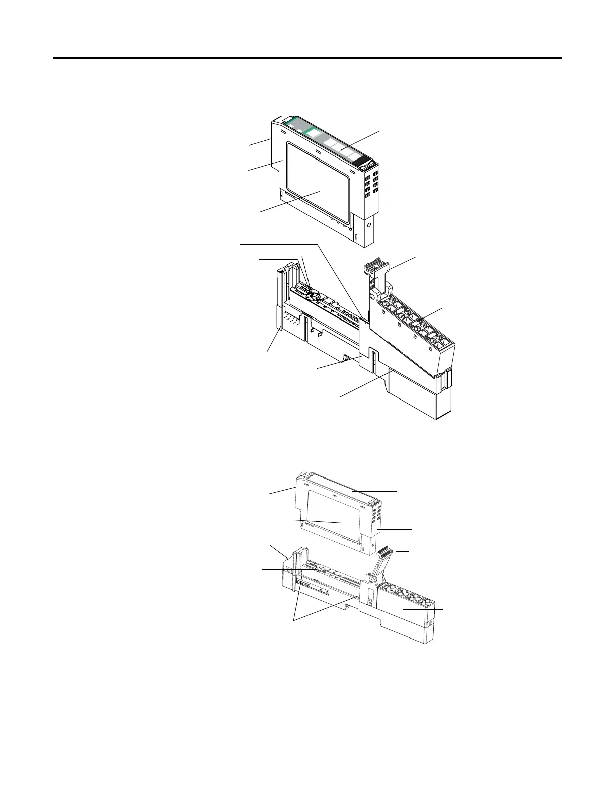
24VDC
Source
Output
Module
Status
Network
Status
1734
OB4E
NODE:
0
1
2
3
Mounting Base
Mechanical Keying (orange)
Module Wiring Diagram
1
Module Locking Mechanism
Insertable I/O Module
RTB Removing Handle
Removable Terminal
Block (RTB)
DIN Rail Locking Screw (orange)
Slide-in Writable Label
Interlocking Side Pieces
41820
44221
One-piece Terminal Base
with Screw or Spring
Clamp
Insertable I/O Module
Module Locking Mechanism
Slide-in Writable Label
Interlocking Side Pieces
DIN Rail Locking Screw (orange)
Module Wiring Diagram
Mechanical Keying
(orange)
Handle
 Loading...