Publication 1734-UM001D-EN-P - April 2008
Install POINT I/O Modules 27
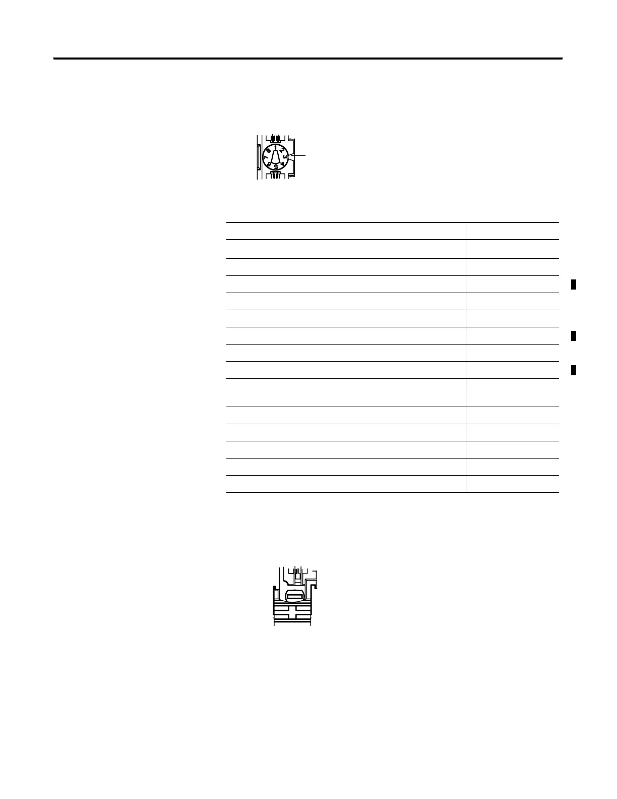
1. Using a bladed screwdriver, rotate the keyswitch on the mounting base
clockwise until the number required for the type of module aligns with
the notch in the base.
2. Make certain the DIN-rail locking screw is in the horizontal position,
noting that you cannot insert the module if the locking mechanism is
unlocked.
Module Keyswitch Position
1734-ARM
(1)
(1)
Use the same keyswitch position as the removed module.
1734-CTM, 1734-VTM 5
1734-IA2, 1734-IA4 8
1734-IB2,1734-IB4, 1734-IB8 1
1734-IE2C, 1734-IE2V 3
1734-IM2, 1734-IM4 8
1734-IV2, 1734-IV4, 1734-IV8 1
1734-OA2, 1734-OA4 8
1734-OB2, 1734-OB4, 1734-OB8, 1734-OB2E, 1734-OB4E,
1734-OB8E
1
1734-OB2EP 1
1734-OE2C, 1734-OE2V 4
1734-OV2E, 1734-OV4E, 1734-OV8E 1
1734-OW2, 1734-OW4 7
1734-OX2 7
Notch
Position 3 is shown.
 Loading...