Publication 1734-UM001D-EN-P - April 2008
36 Install POINT I/O Modules
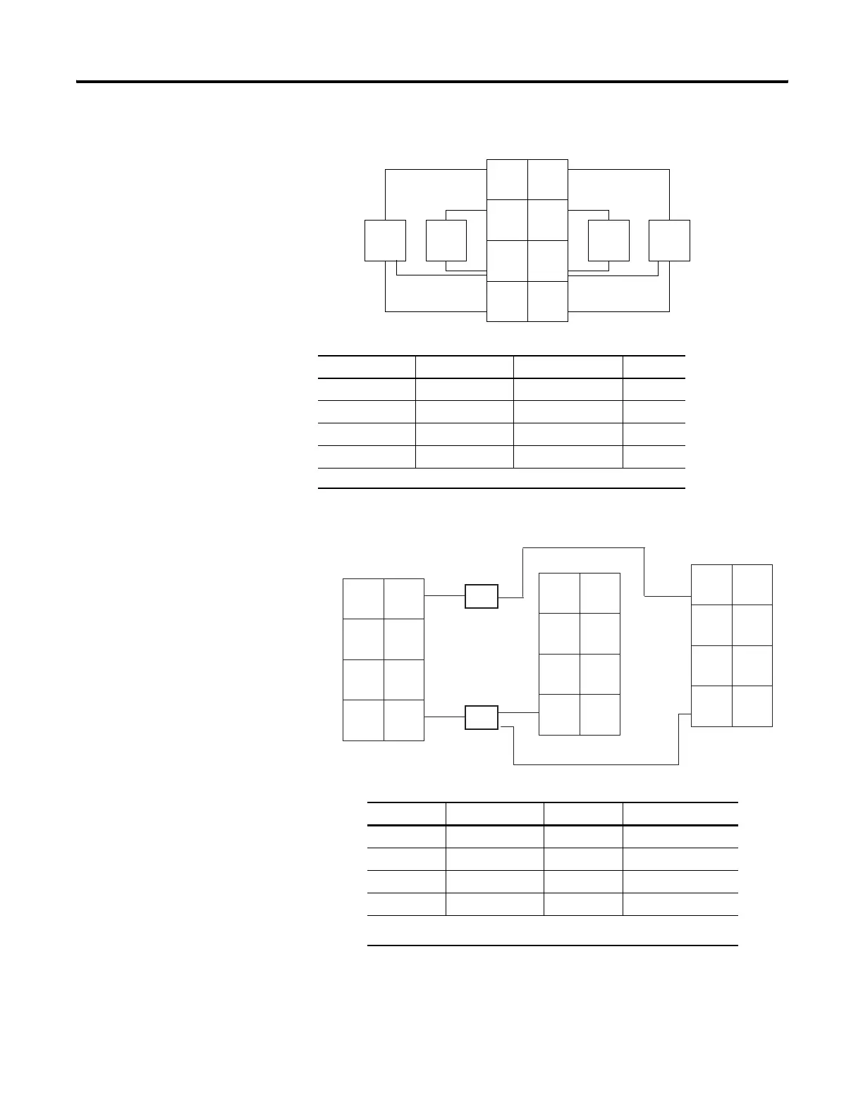
1734-IV4 Module Wiring Diagram
1734-IV8 Module Wiring Diagram
Input Terminal Common Terminal Power
Channel 0 0 4 6
Channel 1 1 5 7
Channel 2 2 4 6
Channel 3 3 5 7
Connect power on 3-wire proximity switches. 12/24V dc is supplied through the internal power bus.
Channel Input Terminal Channel Input Terminal
Channel 0 0 Channel 4 4
Channel 1 1 Channel 5 5
Channel 2 2 Channel 6 6
Channel 3 3 Channel 7 7
Daisychain common and power connections from 1734 Adapter, 1734-FPD, 1734-EP24DC or from user
supplied external auxiliary terminal block.
Prox
In 0 In 1
In 2
C
VV
C
In 3
Prox
ource Input
ProxProx
V = 12/24V dc
C = Common
41969A
3
5
7
0
1
2
4
6
2-wire3-wire
43927
Prox
Prox
3-wire
2-wire
V = Voltage Out
V V
V V
V V
C C
6 7
4 5
2 3
0 1
6 7
4 5
2 3
0 1
6 7
4 5
2 3
0 1
In 0 In 1
In 2 In 3
In 4 In 5
In 6 In 7
V V
C C
C C
C C
1734-CTM
1734-VTM
1734-IV8
Source Input Wiring
C= Common
 Loading...