Publication 1734-UM001D-EN-P - April 2008
Install POINT I/O Modules 39
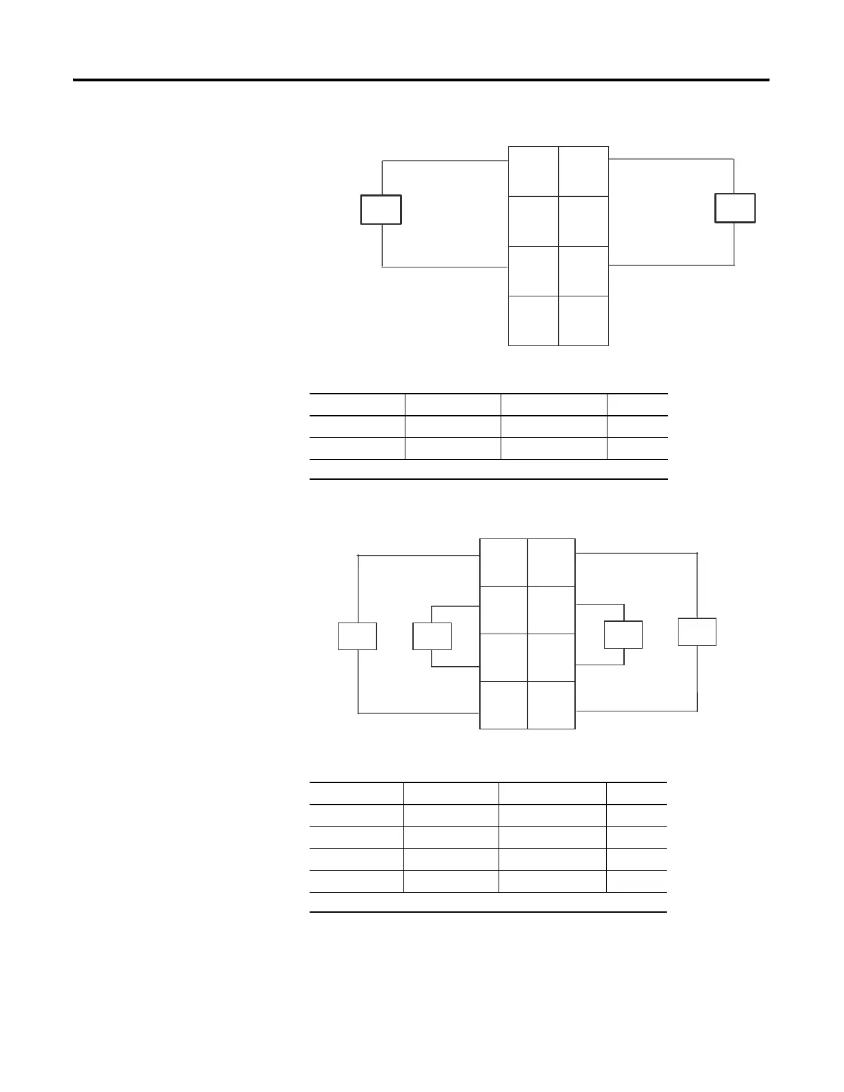
1734-OB2 and 1734-OB2E Module Wiring Diagram
1734-OB4 and 1734-OB4E Module Wiring Diagram
Output Terminal Common Terminal Power
Channel 0 0, 2 4 6
Channel 1 1, 3 5 7
Module power is supplied from the internal power bus.
Output Terminal Common Terminal Power
Channel 0 0 6
Channel 1 1 7
Channel 2 2 4
Channel 3 3 5
Module power is supplied from internal power bus.
Out 0
Out 1
Out 1
Out 0
CC
V
V
44338
0
2
6
4
3
5
7
1
V = 12/24V dc, C = Common
Field power is supplied from internal power bus
Load
Load
Out 0
Out 1
Out 3
Out 2
CC
CC
44339
V = 12/24V dc,
C = Common
Field power is supplied from internal power bus
0
2
6
3
1
7
4
5
Load Load
Load
Load
 Loading...