Publication 1734-UM001D-EN-P - April 2008
84 Install POINTBlock I/O Modules
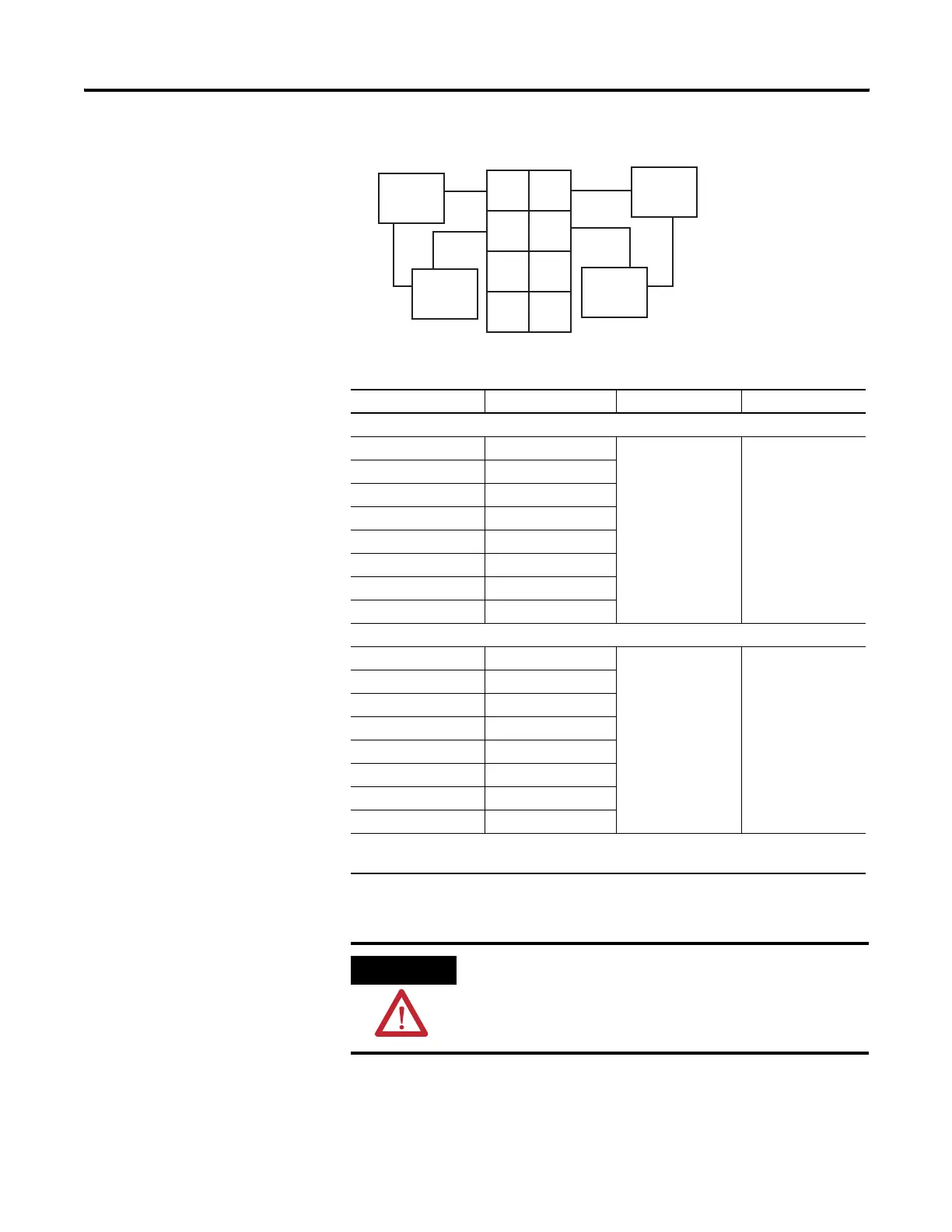
Output Wiring Diagram
(Load Powered by External Power)
Channel Output Common Supply
Remote Termination Block 3
0A 0 Not used Not used
0B 2
1A 1
1B 3
2A 4
2B 6
3A 5
3B 7
Remote Termination Block 4
4A 0 Not used Not used
4B 2
5A 1
5B 3
6A 4
6B 6
7A 5
7B 7
Supply voltage can range from +5V dc to 240V ac, depending on relay load.
12/24V dc power for the module is provided by the internal power bus.
ATTENTION
When connecting more then one wire in a termination point,
make sure that both wires are the same gauge and type.
Out
0A
Out
0B
Out
1A
Out
1B
Load
Power
Supply
Out = Output channel relay contacts
Power Supply = can range from +5V dc to 240V ac
C = Common
0
2
4
6
3
5
7
1
Power
Supply
Load
Out
2A
Out
2B
Out
3A
Out
3B
 Loading...