5 – 10 HS40 Service Manual
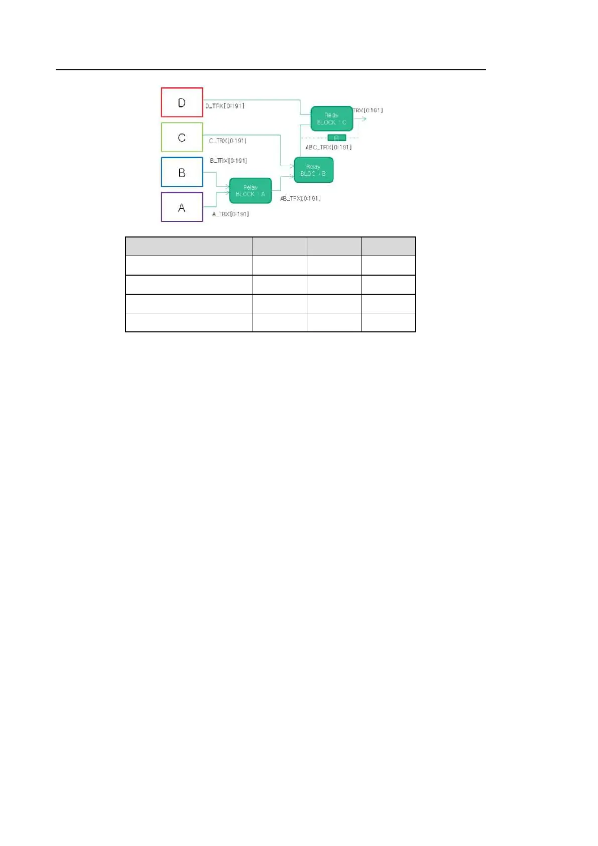
Port SEL A SEL B SEL C
PORT # A 0 0 0
PORT # B 1 0 0
PORT # C 1 1 0
PORT # D 1 1 1
[Figure 5.4 PSA Board Block Diagram]
5.4.1.1. Specification
• 4 Probe Port Support
• CW Pencil Probe Port Support
• Probe Insert Check, ID read, Port selection
• Motor driving signal path for 3D probe
5.4.1.2. Description
■ Probe Selection
It consists of circuits to choose one of four probes. It can use the relay of the latched type to
select a probe chosen by user.
The relay is operated by the probe select signal transmitted from the control logic (CPLD) of
the CW (Continuous Wave Board). Probe Select signals are connected via the Back Plan
Connector.
■ CW Pencil Probe Connection
The Static CW Probe uses a coax-pin LEMO Connector.
The LEMO Connector is located on a separate Connector Board and is connected to the
PSA via cable.
This connector consists of two coax-pins and six pins. The two coax-pins are used for the
TX/RX of the Static CW, while the six pins are used for the personality of Static Probe.