Confidential
Chapter 3 Connecting Cables
RF4402d Series Installation Manual v1.0 64
Copyright © 2018, All Rights Reserved.
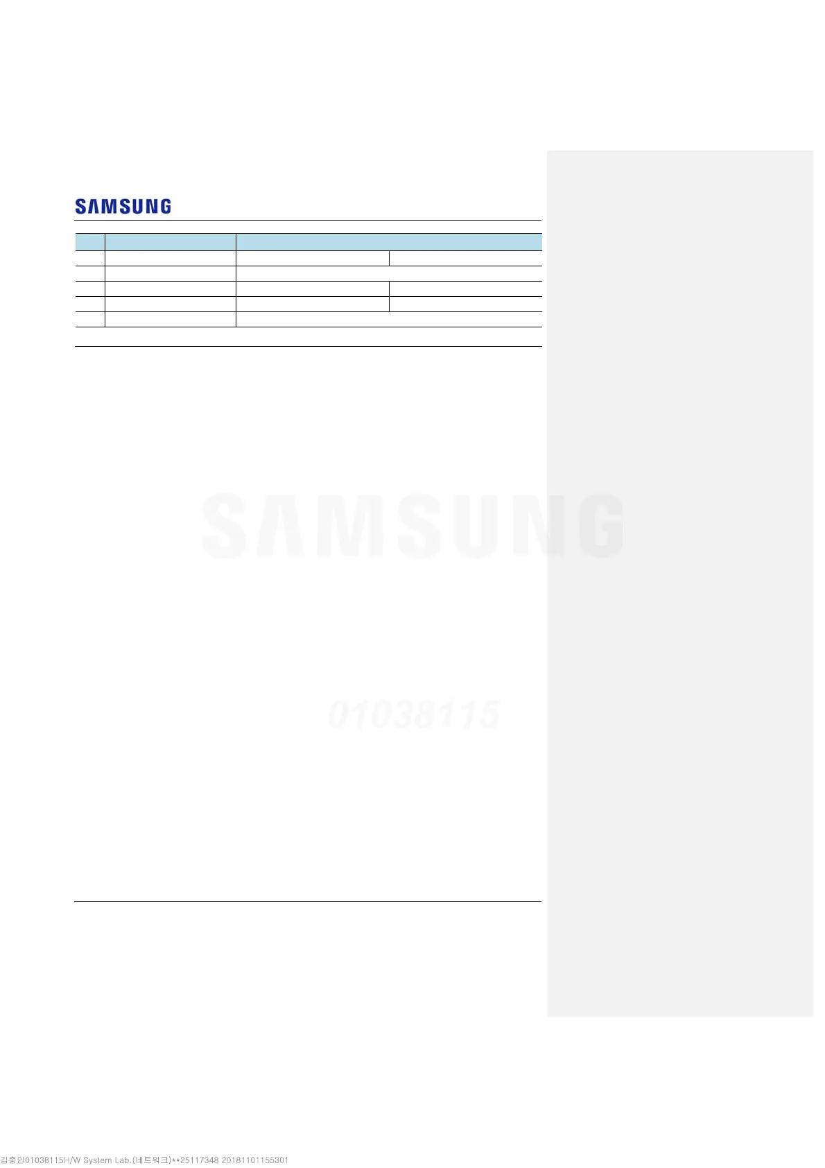
No Type Allowed Cable Bend Radius
3 DC Power Cable Operation: 8 × OD Installation: 12 × OD
4 Optical Cable (Outdoor) 10 × OD
5 UDA Cable Operation: 5 × OD Installation: 10 × OD
6 RET Cable Operation: 8 × OD Installation: 12 × OD
7 1/2 in. Feeder Line (Flexible) 125 mm
* If the allowed cable bend radius is specified by the manufacturer, comply with the bend radius specified.
Cable Binding
Cable binding involves fixing and arranging an installed cable using binding
thread, cable ties, binding wire, and ram clamps, and so on.
Follow these guidelines when binding a cable.
Be careful not to damage the cable during binding.
Use appropriate cable binding tools according to the target location (indoor or
outdoor, and so on) and the type of the cable (power supply cable, optical
cable, feeder line, and so on).
Do not let the cutting section of a cable tie and binding line, and so on be
exposed to the outside. This may cause damage to cables or personal injury.
Make sure that the cutting sections of cable ties and binding lines, and so on
are not exposed to the outside.
Cut off the remainder of the cable thread by leaving about 50 mm of extra
length to prevent the knot from easily getting untied.
If there is a danger that contact failure may occur in a connector connection
due to tension, bind the cable at the closest location to the connector.
Connector Attachment
Connector attachment involves assembling a connector to an installed cable or to a
device on the site.
Follow these guidelines when attaching a connector.
Make sure operator is fully aware of the connector assembly method before
assembling a connector. Assemble the connector in accordance with its pin
map.
Each connector has a hook to prevent its core positions from being changed.
Check the corresponding grooves before connecting a connector to another
connector.
Use a heat shrink tube at a connector connection for cables that are installed
outdoor, such as feeder lines, to prevent water leakage and corrosion from
occurring at the part exposed to the outside.
Connect each cable of the connector assembly in a straight line.