Date Code 20080110 Protection Functions 3-21
SEL-387E Instruction Manual
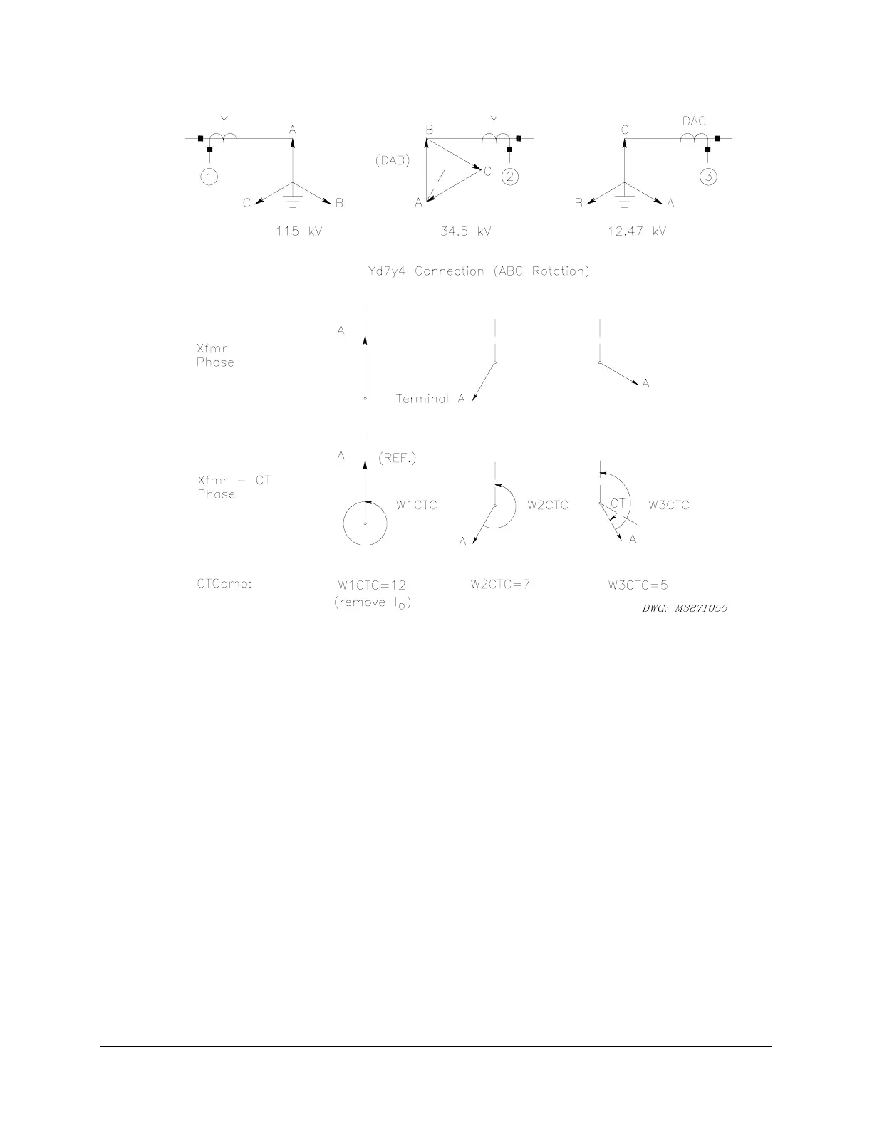
Figure 3.10: Example 2 for WnCTC Selection
1. Establish the phase direction for the three A line terminals. Figure 3.10 shows these
phase directions in the first line below the transformer drawing. Based on the
transformer designation, the terminal directions are shown at “noon,” “7 o’clock,” and “4
o’clock.”
2. Adjust the transformer winding directions based on the CT connections. Windings 1 and
2 need no correction, because they both have wye-connected CTs. Winding 3 has DAC
delta-connected CTs and needs adjustment. Refer to
Figure 3.8 and note that the DAC
connection produces a 30-degree shift in the CW direction for ABC phase rotation. In
the second line under the transformer drawings,
Figure 3.10 indicates this adjustment as a
rotation of the Winding 3 direction from the “4 o’clock” to the “5 o’clock” position.
3. Select a reference direction. In this example we have chosen the primary winding
position at “noon.”
4. Select values of W
n
CTC for each winding. For the sake of later discussion, we have
selected W1CTC = 0 as the setting for Winding 1, the reference winding. Beginning at
the Winding 2 direction at “7 o’clock,” adjust the Winding 2 position in the CCW
direction until arrival at the “noon” reference direction. This procedure requires seven
30-degree increments, or seven “hours” of adjustment. Thus, we choose W2CTC = 7 as
the setting. Similarly for Winding 3, we need an adjustment of five “hours,” so we