Section 05 FUEL SYSTEM
Sub-Section 03 (AIR INTAKE)
05-03-2
REMOVAL
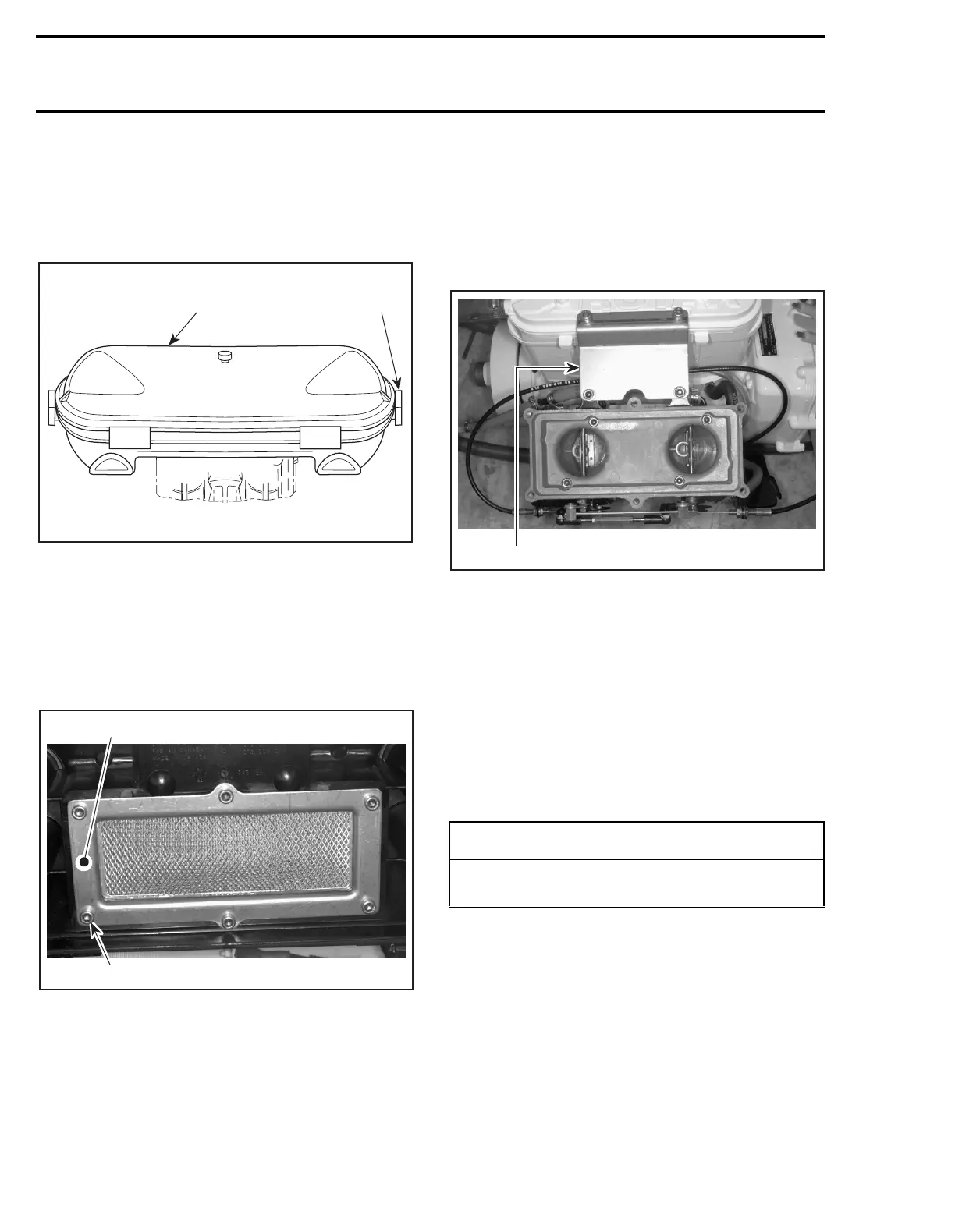
1, Air Intake Silencer Cover
Unlock retaining slides holding air intake silencer
cover and remove cover.
TYPICAL
1. Air intake silencer cover
2. Unlock
4, Air Intake Silencer Base
Remove screws
no. 2
of retaining plate
no. 3
.
Pull out retaining plate
no. 3
and air intake silencer
base
no. 4
.
1. Retaining plate
2. Remove screws
7, Flame Arrester Base
Remove flame arrester
no. 5
.
Remove screws
no. 8
retaining support
no. 6
of
flame arrester base to the cylinder head cover
(717 engines) or to the exhaust manifold (787 en-
gine).
1. Remove support
Remove screws
no. 10
from flame arrester base
then withdraw base.
NOTE:
On single Mikuni carburetor models, re-
move choke and throttle cables from flame arrest-
er base.
ASSEMBLY
Assembly is essentially the reverse of removal
procedures. However pay particular attention to
the following.
7, Flame Arrester Base
Apply Loctite 515 on mating surfaces of flame ar-
rester base.
Apply Loctite 242 (blue) on screws
no. 10
and
torque to 10 N•m (88 lbf•
in
).
F01F2OA
12
F00F02A
1
2
-
CAUTION
Do not modify air intake system, otherwise
calibration will be affected.
F00F03A
1
 Loading...