Section 03 ENGINE
Sub-Section 04 (MAGNETO SYSTEM)
03-04-8
– Uncrimp and unsolder ground wire (BLACK)
from coil core.
1. Uncrimp and unsolder ground wire (BLACK)
2. Uncrimp and unsolder YELLOW and YELLOW/BLACK wires
ASSEMBLY
717 Engines
11, Generating Coil
Strip end of old wire then crimp and solder on
new coil.
Apply Loctite 242 (blue) to screws
no. 12
and in-
stall the new coil on armature plate.
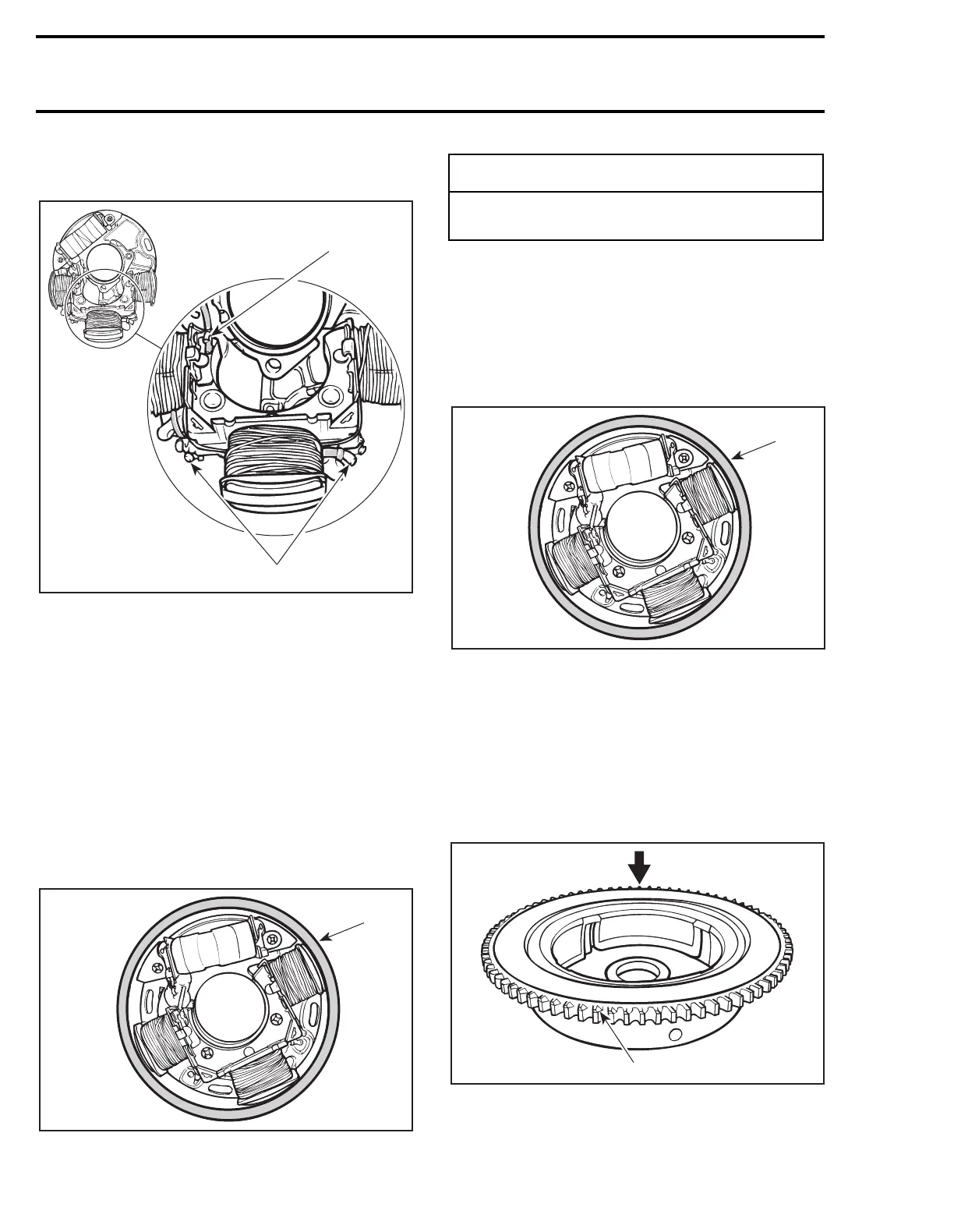
Use magneto coil centering tool (P/N 290 876
922) and install so that it fits around armature
plate before tightening screws.
1. Magneto coil centering tool (P/N 290 876 922)
13, Battery Charging Coil
Position new coil, crimp and solder all wires.
Prior to assembly, apply Loctite 242 (blue).
Use magneto coil centering tool (P/N 290 876
922) and install it so that it fits around armature
plate before tightening screws
no. 14
.
1. Magneto coil centering tool (P/N 290 876 922)
4,5, Magneto Flywheel and Ring Gear
Apply Loctite 648 (green) to magneto flywheel
mating surface. Lay ring gear on a steel plate,
then heat with a propane torch in order to install it
on magneto flywheel.
Pay particular attention to position ring gear teeth
chamfer side as per following illustration.
1. Teeth chamfer
NOTE:
Ensure that ring gear contacts magneto
flywheel flange.
A25E0SA
1
2
F00D0AA
1
-
CAUTION
Before reinstalling the magneto, remove the
loose epoxy from harness.
F00D0AA
1
F01D3BA
1