Section 08 PROPULSION SYSTEM
Sub-Section 04 (REVERSE SYSTEM)
08-04-4
1. Screws, washers and sleeves
6, Reverse Support
For reverse support installation, torque screw to
8 N•m (71 lbf•
in
) and Allen screws to 2 N•m
(18 lbf•
in
).
4,5, Triangular Lever and Sliding Block
Insert bushing in triangular lever and then install
lever to reverse support.
TYPICAL
1. Bushing
Install reverse cable to triangular lever with bush-
ing, plastic washer(s) and flat washers.
Torque cable screw to 7 N•m (62 lbf•
in
).
Torque triangular lever screw to 8 N•m (71 lbf•
in
).
Install sliding block to lever and torque nut to
8 N•m (71 lbf•
in
).
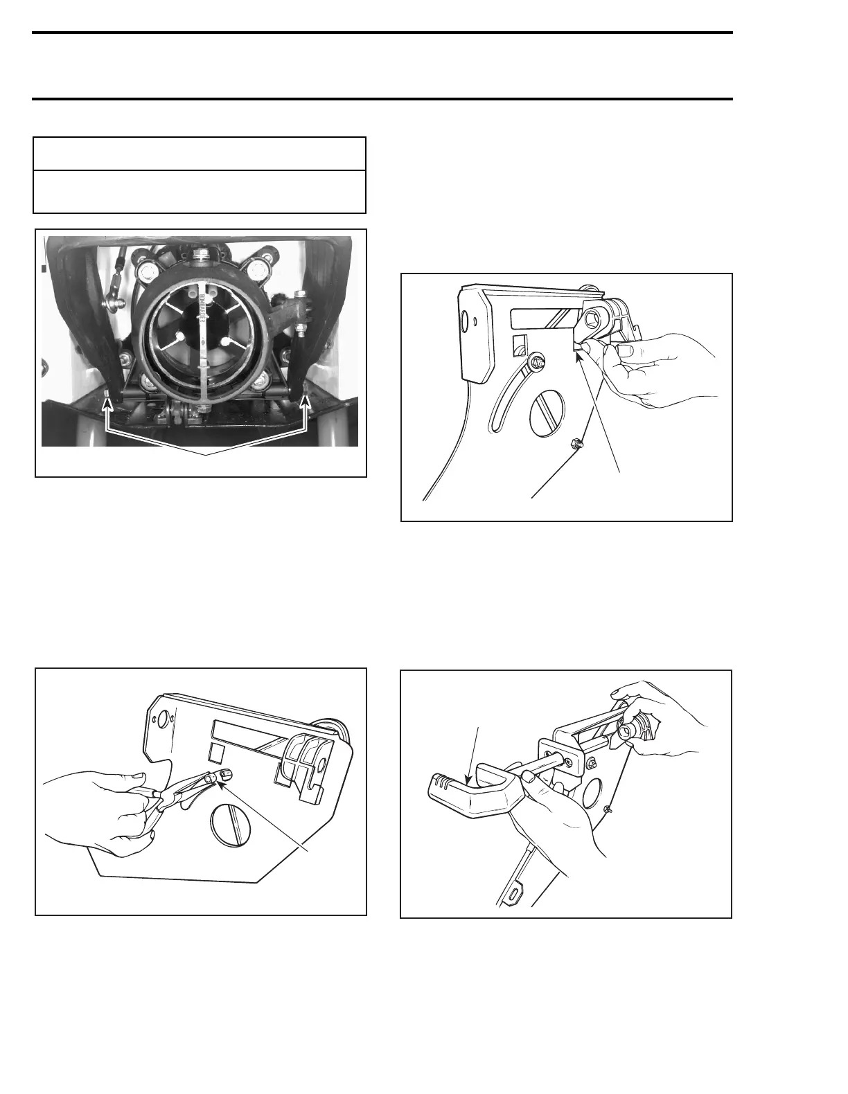
1,5, Locking Lever and Sliding Block
Insert locking lever end in support hole then align
lever and sliding block holes.
TYPICAL
1. Support hole
3, Shift Lever
NOTE:
Always install shift lever with its open end
facing left side of watercraft, then push shift lever
stem through locking lever
no. 1
and sliding block
no. 5
holes.
TYPICAL
1. Install shift lever as shown
-
CAUTION
Always hook reverse gate springs in order to
ease reverse gate operation.
F02J02B
1
F02J0CA
1
F02J0DA
1
F02J0EA
1
 Loading...