Section 08 PROPULSION SYSTEM
Sub-Section 04 (REVERSE SYSTEM)
08-04-5
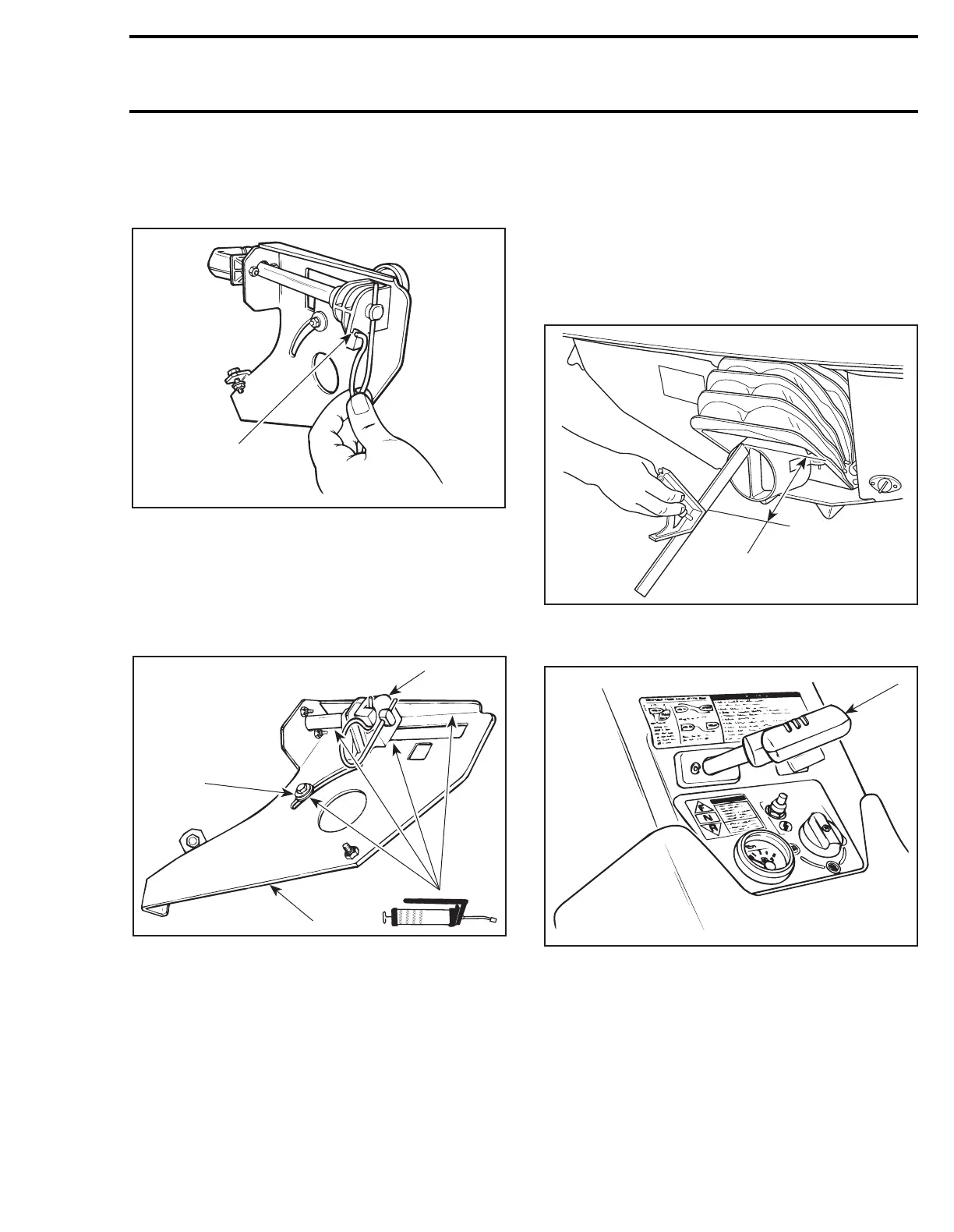
2, Spring
Insert spring in lever stem hole and then install
curved end in sliding block groove.
TYPICAL
1. Sliding block groove
Shift Lever Lubrication
Lubricate sliding block support sliding area and tri-
angular lever with synthetic grease. Also, lubri-
cate sliding washer and shift lever stem.
TYPICAL
1. Sliding washer
2. Sliding block
3. Support plate
ADJUSTMENTS
7, Reverse Gate
Position handlebar in a straight ahead position,
nozzle should be parallel to rear of watercraft.
Using a square, set it to 129 ± 3 mm (5-5/64 ±
7/64 in), then position square end at the top mid-
dle of nozzle.
A. 129 ± 3 mm (5-5/64 ± 7/64 in)
Pull shift lever in REVERSE position.
TYPICAL
1. Shift lever in REVERSE position
With the gate down to REVERSE position it
should be at the specification.
NOTE:
Push slightly on the gate in order to recov-
er spring tension and to obtain proper position of
the gate.
F02J0KA
1
F02D03A
1
2
3
F02J0HA
A
F02J0GA
1
 Loading...