Section 08 PROPULSION SYSTEM
Sub-Section 05 (VARIABLE TRIM SYSTEM)
08-05-2
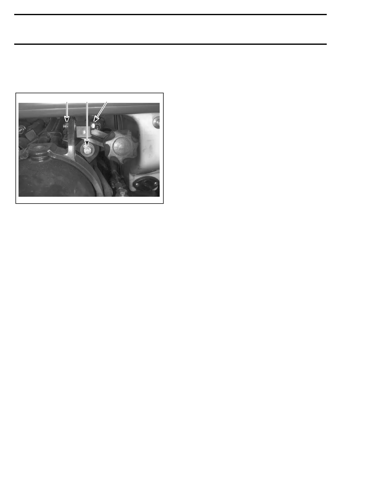
REMOVAL
Loosen screw
no. 1
, bolt
no. 2
and lock nut
no. 3
retaining support from trim ring.
1. Screw
2. Bolt
3. Lock nut
Remove manual trim.
4, Trim Ring
To remove trim ring/nozzle assembly from venturi,
loosen side screws
no. 5
of trim ring.
DISASSEMBLY
Loosen nut
no. 6
from support; then, remove rub-
ber washer
no. 7
and half bushings
no. 8
.
Loosen adjustment screw
no. 9
to remove
threaded pivot
no. 10
.
ASSEMBLY AND INSTALLATION
Assembly and installation are essentially the re-
verse of removal and disassembly procedures.
For torque specifications and service products to
be used, refer to the main illustration at the begin-
ning of this sub-section.
F05J08A
3 1 2