Section 09 STEERING SYSTEM
Sub-Section 03 (GTS MODEL)
09-03-2
REMOVAL AND INSTALLATION
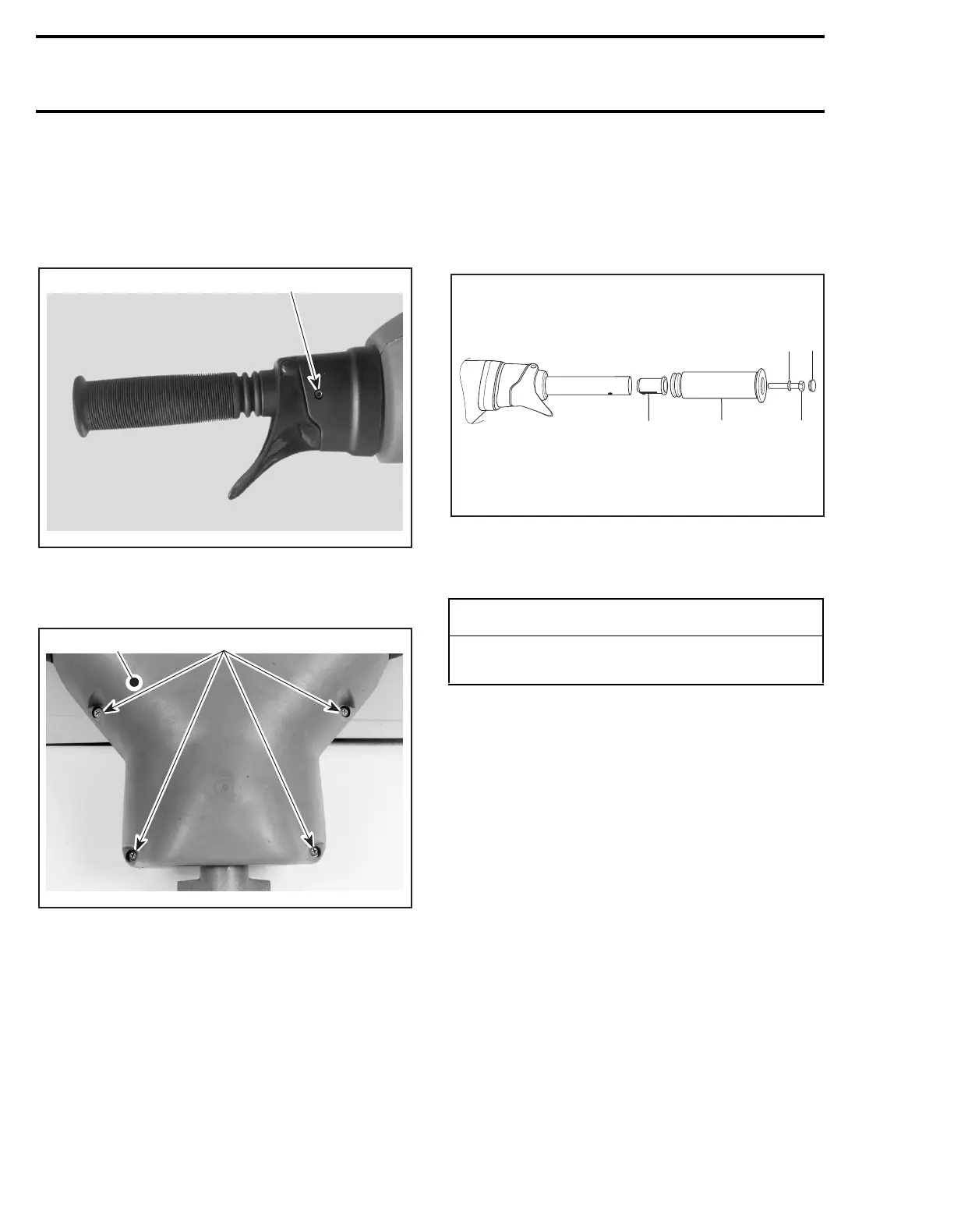
1, Cover
To replace the cover, loosen set screws
no. 30
of
handlebar housing.
1. Set screw
Remove and reinstall 4 screws
no. 2
and washers
no. 3
.
1. Cover
2. Screws
4,8, Grip and Grip Insert
To remove grip, just pull out cap
no. 5
from grip
end and remove screw
no. 6
and washer
no. 7
.
Pull out grip.
To verify grip insert for damage, remove it from
handlebar.
When installing the grip insert in handlebar
no. 29
, ensure that its notch is properly inserted
in the hole beneath the handlebar.
Install grip
no. 4
on handlebar
no. 29
matching it
to the hex form on the grip insert.
Install flat washer
no. 7
and screw
no. 6
.
Torque screw to 14 N•m (10 lbf•ft).
Install cap
no. 5
.
1. Grip insert
2. Grip
3. Flat washer
4. Screw. Torque to 14 N•m (10 lbf•ft)
5. Cap
17,29, Steering Stem and Handlebar
REMOVAL
Disconnect wiring harnesses leading out of dash-
board hole.
Disconnect throttle cable at carburetor.
Remove throttle cable from tie-block and clip.
Unscrew nut
no. 11
retaining locking plate
no. 9
;
then remove locking plate and washers
no. 12
.
Unscrew screw
no. 13
of steering stem arm
no. 10
.
Pull out handlebar and steering stem.
NOTE:
It is not necessary to disconnect steering
cable to remove handlebar and steering stem.
28, Bushing
Inspect bushings for wear, cracks, scoring, etc.
Replace as necessary.
F00K01A
1
F00K02A
2
1
-
CAUTION
Ensure to install flat washer otherwise screw
will damage grip end.
F01K1PA
1
2
3
4
5