Section 05 FUEL SYSTEM
Sub-Section 04 (CARBURETORS)
05-04-5
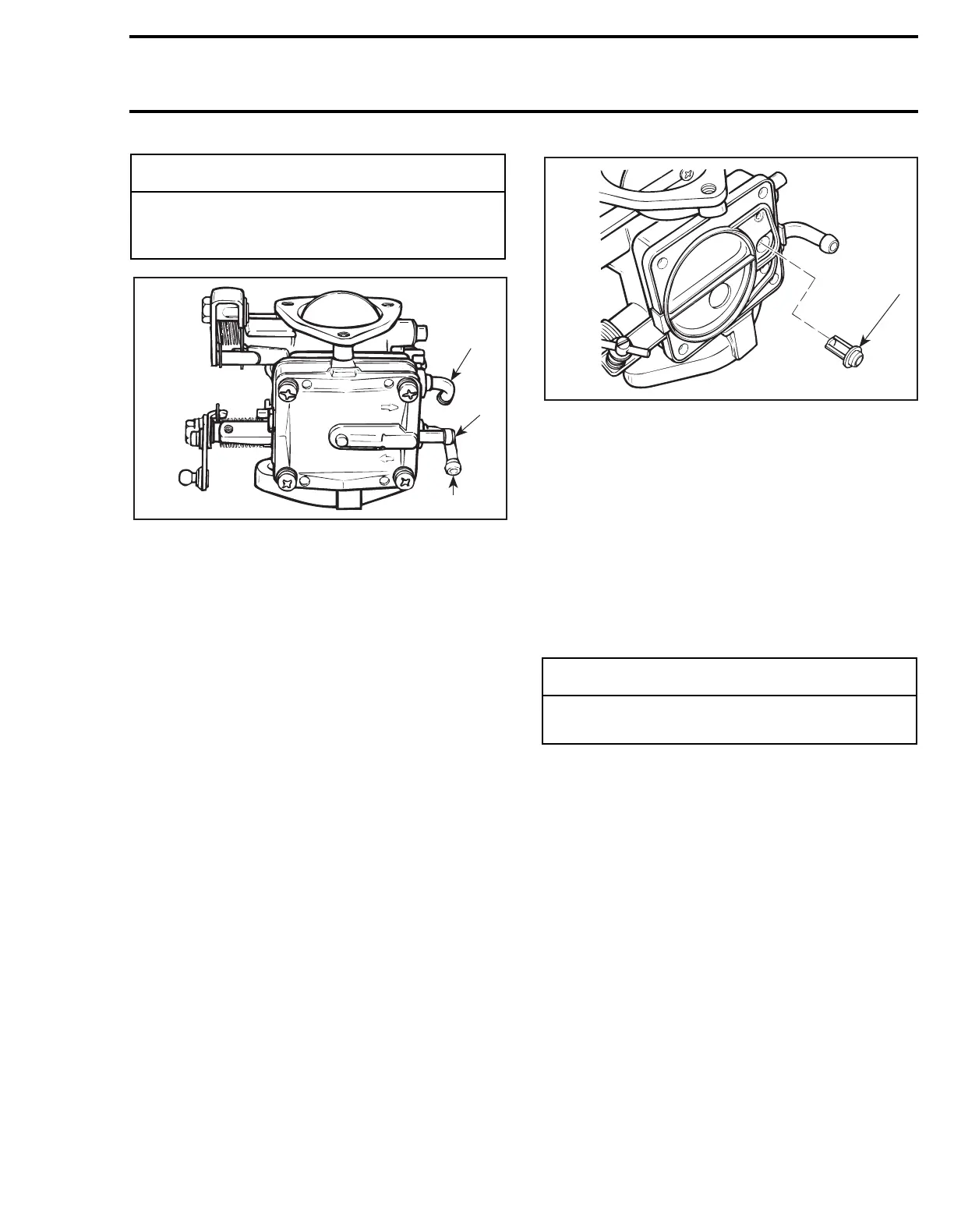
TYPICAL
1. Fuel outlet nipple
2. Pulse nipple
3. Inlet nipple
Repeat the same procedure at the outlet nipple.
This time the outlet valve should hold with pres-
sure and release under vacuum.
Inspect valves. The pumping area should be free
of holes, tears or imperfections. Replace as needed.
5, Filter
To verify filter condition proceed as follows:
Remove pump cover
no. 16
, gasket
no. 17
, dia-
phragm
no. 18
and then pump body
no. 4
and di-
aphragm
no. 19
.
Remove filter from carburetor body then clean fil-
ter and blow carefully with compressed air (low
pressure).
Replace filter if damaged.
TYPICAL
1. Filter
ASSEMBLY
When assembling pump, ensure to properly posi-
tion components together. Refer to previous illus-
trations if necessary.
6,7, Choke Plate and Throttle Plate
When installing plate onto shaft, close plate so
that it centers into carburetor bore. Firmly tighten
screws.
8, Needle Valve Lever
Rounded end of needle valve lever must be flush
with surrounding metering chamber floor and not
with body assembly. Place the end of a ruler over
lever to check adjustment.
◆
WARNING
Some fuel may be present in fuel pump. Be
careful not to swallow fuel when under vac-
uum.
F01F0WA
1
2
3
-
CAUTION
Always apply Loctite 242 (blue) on screw
threads prior to installing screws.
F01F0YA
1