Section 09 STEERING SYSTEM
Sub-Section 04 (GS, GSI, GSX, GTI AND GTX MODELS)
09-04-4
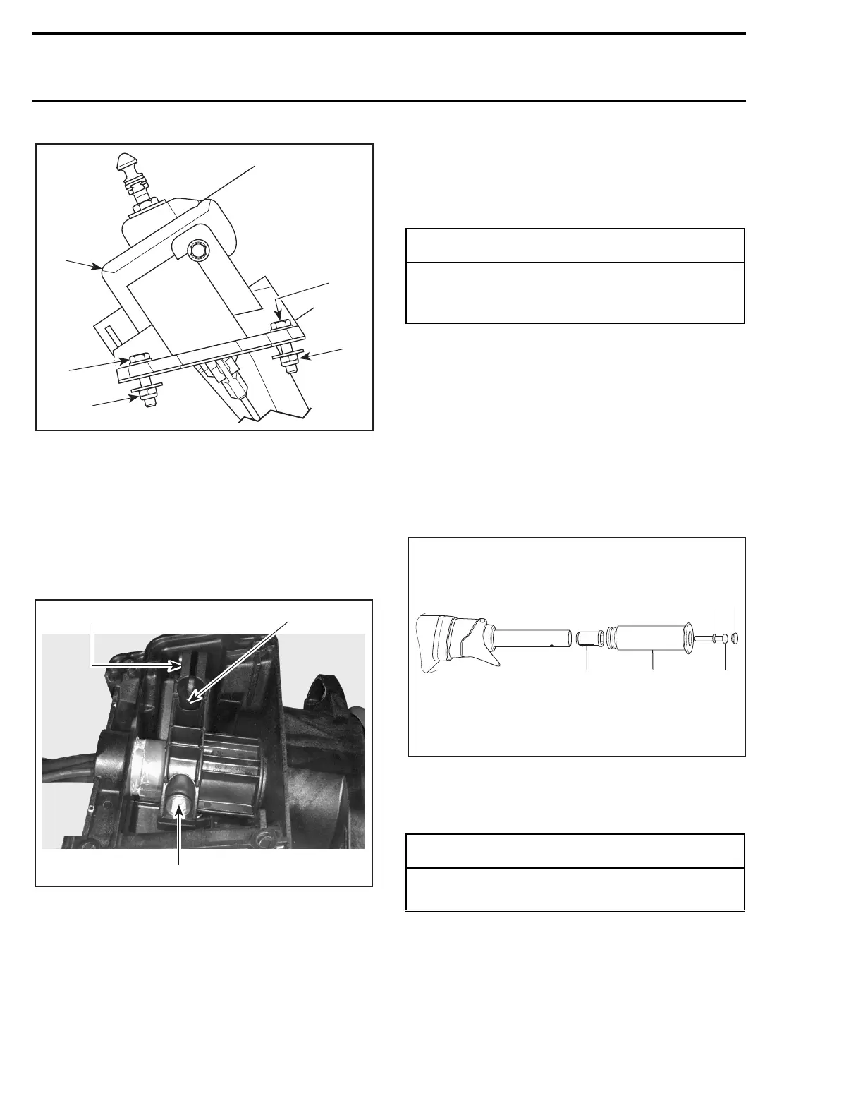
1. Steering support
2. Bolt
3. Lock nut
Remove steering support with handlebar, wiring
harnesses and cables.
15,16, Steering Stem Arm and Support
Loosen bolts
no. 17
retaining steering stem arm
to support.
1. Steering stem arm
2. Bolt
Remove steering stem arm and support.
ASSEMBLY
Assembly is essentially the reverse of disassem-
bly procedures. However, pay particular attention
to the following.
1,21, Grip and Grip Insert
When installing the grip insert
no. 21
in the han-
dlebar
no. 22
, ensure that its notch is properly in-
serted in the hole beneath the handlebar.
Install grip
no. 1
on handlebar
no. 22
matching it
to the hex form on the grip insert.
Install flat washer
no. 23
and screw
no. 3
.
Torque screw to 14 N•m (10 lbf•ft).
Install cap
no. 2
.
1. Grip insert
2. Grip
3. Flat washer
4. Screw. Torque to 14 N•m (10 lbf•ft)
5. Cap
1
F07K07A
2
3
2
3
F07K08A
2
1
2
-
CAUTION
Apply all specified torques and service prod-
ucts as per main illustration at the beginning
of this sub-section.
-
CAUTION
Ensure to install flat washer otherwise screw
will damage grip end.
F01K1PA
1
2
3
4
5
 Loading...