Section 08 PROPULSION SYSTEM
Sub-Section 03 (DRIVE SYSTEM)
08-03-8
SPX, GSX AND GTX MODELS
1. PTO flywheel remover
Install the extension handle (P/N 295 000 125) on
the PTO flywheel remover. Loosen PTO flywheel
COUNTERCLOCKWISE when facing it.
DISASSEMBLY
HX and XP Models
13,14, Seal and Needle Bearing
Bearing and seals can be easily removed using
the bearing/seal remover tool (P/N 295 000 144).
NOTE:
The same tool is used for bearing and seal
removal of jet pump.
Properly support seal carrier when removing seals
and bearing.
PARTS INSPECTION
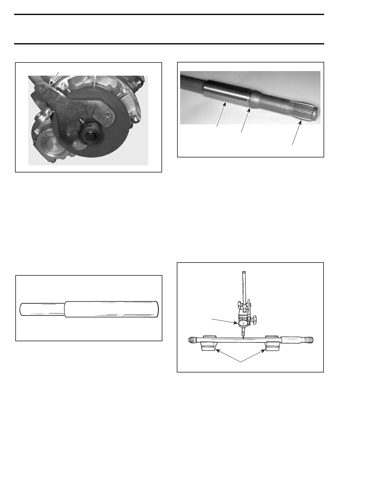
3, Drive Shaft
Inspect condition of splines.
Inspect condition of groove.
With your finger nail, feel contact surface of float-
ing ring. If any irregular surface is found, renew
drive shaft.
1. Floating ring contact surface
2. Groove condition
3. Splines condition
Excessive deflection could cause vibration and
damage to drive shaft splines, impeller, flywheel
or floating ring.
Place drive shaft on V-blocks and set-up a dial
gauge in center of shaft. Slowly rotate shaft; dif-
ference between highest and lowest dial gauge
reading is deflection. Refer to the following illus-
tration.
Maximum permissible deflection is 0.5 mm
(.020 in).
MEASURING DRIVE SHAFT DEFLECTION
1. Dial gauge
2. V-blocks
15, Damper
Visually inspect shape of dampers for deformation
or other damage.
F06I02A
1
F01J11A
F01I0FA
3
2
1
F01J15A
1
2